
Artificial Vision: AINECC Color Model in Edge Detection
4.94/5 (11 votes)
Artificial Vision: AINECC color model in edge detection. Entirely OpenCV code.
- Download source code - 145.15 KB
- Download EXE - 2.06 MB
- Download Microsoft Visual C++ Redistributable 2008 (Better if you do it from Microsoft) - 1.71 MB
Introduction
There are some problems when an system (natural or artificial) tries to extract an object from the scene’s background “Background Subtraction”.
One of the most ancient methods (before the software engineers), was assuming that the object (or part of it), has regions of constant wavelength reflection (color) .
AINECC is a personal project, really complex in some subjects, with a different way of facing the computer vision theory in an intelligent and evolutionary system. The target will be reached when a low cost robotic arm connected to a webcam, can place by itself, the chess pieces coming from the box in its place on the board.
The code shown here is only part of it and was extracted for educational purposes.
This code includes a new color model, an algorithm for the first step in the background subtraction, and two usual ways for border detection: Sobel and the maximum difference between the neighboring pixels.
The Color Model
A “color model” is a mathematical way to describe the color of the light captured by electronic sensors.
There are a lot of color models depending on the purpose to be used for. Usually, the researchers are looking for getting the best color accuracy.
Mostly, color models algorithm has reverse formula, but for this project this aspect was not considered in order to improve the results.
Basically the color model used in AINECC project converts each lineal color range RGB in an tangent curve RGB normalized to fit it in the range: Real(0,1)
xc = aTan(x/(y*z))/(Pi/2) (see below 3D curve for the Red color)

The first problem is how to get the color from the object.
The usual way to do that is by converting RGV values in HSV (Hue, Saturation, Value), where Hue is providing the color value.
The best way to extract uniform color from the object without illumination influence could be by processing each pixel vector RGB: R(rx,ry,rz), G(gx,gy,gz), B(bx,by,bz); really hard to do. There are many other studies dealing with it and focusing the problem.
This project sets the idea that it is possible to use a simple division to get a real relation between colors.
The second problem is the noise.
Usually Hue extraction is affected by the noise when the RGB values are low or close to the white.
This project tries to solve this problem inverting the illumination level but keeping color level in the right direction.
The source code was based entirely in the opencv Library 2.0 including image and video capture. Opencv looks weak when trying to managed camera setup or video format, but on the other hand, thanks to opencv it's simple to capture or extract an image or frames and for sure, it is really strong to process the image captured.
If you need more, try DirectDraw (Microsoft example: amcap source code).
Using the Code
This code has been developed under the MFC (Microsoft Foundation Classes) platform and using opencv (Open Computer Vision Library).
The application has one main dialog. This main dialog has 3 windows: Source, Color Model and Edge detection.

But let’s explain the code running the application.
Steps to Run the Application
- 1st – Test configuration parameters (or play with them)
- 2nd – Push [Open Video]
- 3rd – Play with the color model and the edge parameters in real time
- 4th – Push [Close Video] or [Exit] to close or exit from the application
Configuration Parameters
Below the source window there are some parameters addressing “Camera” or “Image” configuration:
- Camera:
Width, Height and FPS; are typical camera setup parameters. If you are lucky maybe FPS is going to your camera, if not the 30 is going to be showed on the dialog after it starts.
I have no idea how to get the good “Width” and “Height” values using just opencv, anyhow that problem does not bother me because if a wrong data is put in, the camera changes its parameter to the closed one, then the real result will overwrite the “edit control” and it works. Remember to useDirectDrawfor improved camera control.
Color model is “read only” parameter. This code works only with RGB 8U (RGB24) cameras, webcam included. - Image:
Really there are two images: the color model and the edge detection. By writing “Width”, and “Height” parameters, the size of the images to be processed will be changed. It could be nice to reduce “processor load” and get better reading of frames per second (FPS).
The “color” affects both images. - 3RGB->1BW 8: (Color => RGB 8U, Edge => BW 8U). The “edge” are detected in each channel independently and then mixed in one.
- RGB 8U: (Color => RGB 8U, Edge => RGB 8U). The “edge” are detected in each channel independently and shown in a RGB image.
- BW 8U: (Color => BW 8U, Edge => BW 8U). This mode simulates Black and White cameras (BW). Both “Color” and “Edge” images are treated in one Gray channel.
The “Configuration’s parameters” can be set while video is off. When video is open, those values are tested with the camera and finally blocked.
Opening Video
Pushing [Open Video], the application itself starts. Really the code is “enclosed” inside the function “OnBnClickedButtonOpenVid”.
To keep it alive this function a loop “While(1)” is used.
Inside this function, there is a jump to 3 algorithms:
//
	ainGetColor8U( IplImage* srcCo8Uarr, IplImage* dstCo8Uarr, int code);
	ainGetDifer8U( IplImage* srcDifArr, IplImage* dstDifArr, int code);
	aiSobel8UC3( CvArr* src, CvArr* dst, int xorder,
		int yorder, int aperture_size CV_DEFAULT(3));
//
ainGetColor8U and ainGetDifer8U were made using opencv’s "rookie mode", while aiSobel8UC3 was made using the opencv developer way. I could not detect the difference in processor load, maybe you will.
ainImgInCVWnd is an auxiliary function. This function gets the “image” and adjusts its size to fit it and to view it in its window.
Screenshots
Samples of images captured.
Source:
Environment:
Room lighting: 300 Lux
Object lighting: One spotlight 1000 lux

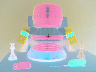
Color Model RGB 8U:

Edge detection.
When the difference between pixel around the central pixel is higher than 2%, then a black point is put on the edge image in the same place that the pixel analyzed.

Color Model RGB to BW.
This color mode is useful when Red Green and Blue colors are analyzed separately, I mean, when only the dominant color is going to be treated.
This mode is the best one for computer vision.

And its Sobel result:
