
Beginner's Guide to using the Bluetooth HC-05 Module with an Arduino Uno
How to send data from a TMP36 to a Bluetooth terminal using the HC-05 module
Introduction
In this article, I will demonstrate how to establish a bluetooth connection with your Arduino by using the Bluetooth HC-05 module. We will collect data from a TMP36 temperature sensor and then display that data in a bluetooth terminal. All of the supplies needed to use the HC-05 module will be listed in the "Materials" section below. After completing this tutorial, you will be able to send information from your Arduino Uno to a bluetooth terminal. Please note that this tutorial is meant for people with little experience with the Arduino Uno, so I will try my best to go over all of the materials used in detail. Now without further delay, let's get started!
Powering the Arduino
The first thing that we want to do is make sure we can supply voltage to the Arduino and to the HC-05 module, but let's start first with the Arduino Uno. The Ardiuno needs a power supply between 7-12 volts in order to work properly and to get this voltage, simply plug in the Arduino's power cable into a USB port on your computer/laptop. Although there are other ways to power our Arduino, we will be using this method because it will allow us to upload code later in the tutorial.
NOTE: Do NOT work on the Arduino while it is powered on, we are simply setting this up for later use. As of right now, set the Aduino's power cord aside and after we have finished setting up the HC-05 module, we will supply power.
Now we want to supply power to the HC-05 module and to do this, we are going to use a few wires and a breadboard. Breadboards are units that allow us to build temporary circuits with no sodering, which makes them great for testing new components for your Arduino Uno. First, connect one end of a wire to the section on the Arduino board that says "5V", then connect the other end to any hole on the very bottom row. Next, take another wire and connect one end to the Arduino pin which says "GND" and connect the other end to any hole on the row with the minus sign next to it. You should get something similar to this...
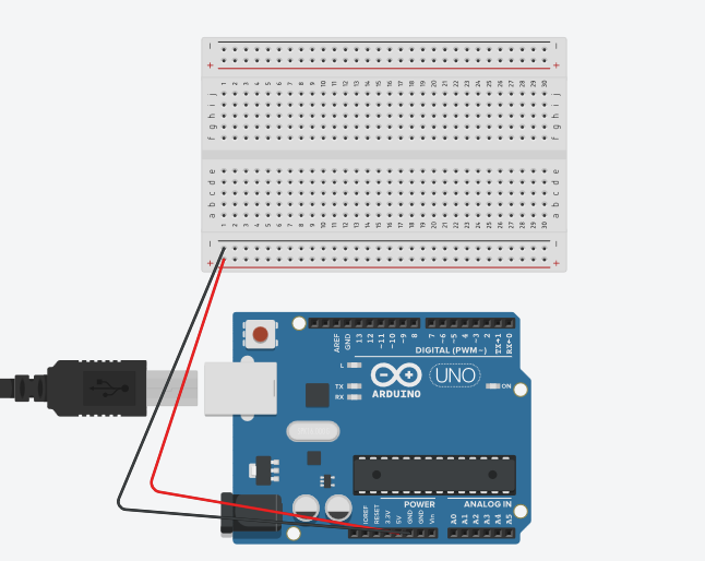
The row with the red line next to it is called a power rail and we use it to supply power to all of our components. Any wire that is connected to that row can also get access to 5 volts allowing us to power multiple components at once. The row above power rail connects all components to the grounding pin of the Arduino and it is called the ground rail. Now that we can supply power to our bluetooth module, let's go over all of the pins and see what they do.
The Bluetooth Module
As mentioned before, the HC-05 bluetooth module allows us to establish a bluetooth connection, but before we connect it to the Arduino, let's go over the HC-05 schematic.

Don't worry about the first and last pin of the bluetooth module since we will not use them for this tutorial, the rest of the pins and their functions are listed below.
- RXD: This is the receiver pin of the module, its job is to collect data and it plugs into the Arduino's Transmitter pin(TX).
- TXD: This is the transmitter pin of the module, its job is to send out the data it receives and it plugs into the Arduino's Receiver pin(RX).
- GND: This is the grounding pin of the module, its job is to ground the voltage the VCC pin receives and it plugs into the ground rail on the breadboard.
- VCC: This is the voltage pin of the module, its job is to get voltage from the Arduino and it plugs into the power rail on the breadboard.
Now that we know what each of the pins does, we can add the wires needed to get them to work, however let's start with the RXD pin first because it needs a special voltage. So in order to power it, we need to make a voltage divider.
The Voltage Divider
Unlike the other pins of the module, the RXD pin has a logic level* of 3.3 volts and not 5 volts, so because of this, we need to dampen the voltage that the RXD pin receives by using a voltage divider. A voltage divider is simply two resistors in series, however we will use a wire in between the two resistors to connect with the RXD pin and the rest of the voltage will go to ground. Set up your circuit like so...

NOTE: The resistor that is closest to the Arduino is a 2k Ohm resistor and the resistor farther away from the board is a 3k Ohm resistor, also the RXD pin will be located at position C25 (column C, row 25).
* A logic level is the specific voltage at which a signal can exist. In other words, a signal can exist either as a "High" state or a "Low" state, so if our logic level is 3.3v then a 3.3 volt signal is considered a "High" state to the device and a 0 volt signal is considered a "Low" state. Supplying a device voltage that is past its logic level can damage the device permanently.
The Remaining Pins
To connect the remaining pins to their respected places, follow the bullet points in the Bluetooth Module section, after you've finished, your circuit board should look something like this:

Note: Place the RXD pin at position (C25), the TXD pin at (C26), the GND pin at (C27), and the VCC pin at (C28).
TMP36
Next, we are going to install the TMP36 to our Arduino board. This device will allow us to record the temperature of the environment around us and we will send this data to the bluetooth terminal, but before we begin, let's quickly go over the TMP36 pins from left to right.
- V in: "V in" stands for "Voltage In" and as the name suggests, the job of this pin is to take in voltage that the TMP36 can use.
- V out: "V out" stands for "Voltage out" and this is the pin that we will use to read the results of the sensor. You can connect this pin to any one of your digital pins.
- GND: This is the ground pin of the TMP36 sensor, and its job is to ground the voltage that the TMP36 received.
Now that we have discussed the pins of the TMP36 and their functions, lets connect the TMP36 to our breadboard. Also, please note that we will be using analog pin 0 with the sensor, but if you wish to use another pin that is perfectly fine, just remember to declare this pin in your Arduino code.

Congratulations! You have made it past the hardware part of setting up an HC-05 module. Next, we will jump in the software aspect of setting up the module and program the Arduino to communicate to a bluetooth terminal using the module.
Software
The Code
Now we are going to display the results of the TMP36 to the Bluetooth terminal using the HC-05 module. Open your Arduino IDE, create a new file, and copy the following code.
int sensorPin = 0;

void setup() {
  Serial.begin(9600); // Default communication rate of the Bluetooth module
}

void loop() {
  int sensorVal = analogRead(sensorPin); //read the input from the sensor
  float voltage = (sensorVal/1024.0) * 5; //convert the input into a voltage
  float temperatureCelsius = (voltage - .5) * 100; //convert voltage into temperature

  if(Serial.available() > 0) {
  Serial.println(temperatureCelsius); //print results in bluetooth terminal
  delay(100);
 }
}
Before we upload the code to our Arduino, I will briefly go over what is in this program. First, we initialize the analog pin by setting an integer to zero. Then, in our setup function, we set the communication rate to 9600baud which is the default rate for bluetooth communication. After that, we gather the data from the sensor, convert that data to volts and then convert those volts to a readable temperature in degrees Celsius. Finally, we print the results to our bluetooth terminal if our phone is reading for communication.
Now that we have our code and understand what is does, we are ready to upload the code to our Arduino Uno. Follow the lists below to upload your Arduino code to the board.
- Plug in your Arduino into one of the USB ports on your electronic device (you should see a green light on your Arduino board if you have done this successfully).
- Open your Arduino IDE and go to Tools -> Boards and make sure that "Arduino/Geniuno Uno" is selected.
- Next press the Upload button that is located next to the Verify button.

Congratulations! You have completed the Software part of this tutorial. In our next and final part, we will set up the bluetooth terminal and establish a bluetooth connection with our Arduino Uno.
Bluetooth Terminal
Installing the App
The first thing that we want to do is to download a bluetooth terminal app that we can use for our Arduino. There are many apps which you can use that are just fine, however just so that all of us are on the same page I recommend using the app Bluetooth Terminal HC-05 by mightyIT.

Establishing a Bluetooth Connection
After our app has been successfully downloaded open, we must connect our Arduino Uno to our phone. First, make sure that your Arduino is powered on. Next, go to your phone's bluetooth settings and press "search", then click on the bluetooth device that ends in HC-05.

You will then be asked to put in a pin for the connection. Simply type in "1234" and press enter. Now you are successfully connected to your bluetooth device!
Using the Bluetooth Terminal
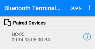
Open the Bluetooth Terminal App we have just downloaded, then under the "Paired Devices" list, you should see your HC-05 module. If you do, click on the HC-05 button and you should see temperature recordings in the bluetooth terminal.
Congratulations! You have successfully established a bluetooth connection with your Arduino Uno using the HC-05 module. Please keep in mind that you can do so much more with the HC-05 module and I encourage you to continue using the HC-05 module and explore more unique ways to use it.
Materials
- 1 Arduino Uno
- 1 Half-sized breadboard
- jumper wires
- TMP36
- 1 Bluetooth Module HC-05
- 1 2k Ohm Resistor
- 1 3k Ohm Resistor
- Arduino IDE (https://www.arduino.cc/en/Main/Software?)