
Getting video stream from USB web-camera on Arduino Due - Part 6: Full USB device configuration
4.27/5 (7 votes)
Building device diagram
Introduction
Part 5 is here.
In previous article I shown how to get some control data from a USB device. In this article I'll show how to get all necessary information from it. This information will be enough to make a decision about video-streaming. Supported frame sizes, video formats, bandwidth, etc. and a device diagram will be shown here.
Configuration
Above mentioned information resides inside USB device configuration. In my device there is only 1 configuration (as was found out in previous article) and if your device has more than one, apply this article to any configuration of your device.
Configuration consists of many descriptors, one of them (the first one) is configuration descriptor. It is not possible to get separately an individual descriptor that is located inside a configuration, however data can be read up to specified size which I'll use later.
Getting configuration size
First task would be to get the total size of the whole configuration, otherwise we could run out of buffer size. Total size is specified inside configuration descriptor [2, p.265] therefore I can read bytes up to the position (including) where total size is located:

wTotalLength field holds needed information which means that reading four bytes only is enough.
Thus I'll create control request that requests specified configuration and read only 4 bytes:
void USBD_GetConfigurationDescriptorBegin(uint16_t TotalLength)
{
    usb_setup_req_t ControlRequest;

    ControlRequest.bmRequestType = USB_REQ_DIR_IN | USB_REQ_TYPE_STANDARD | USB_REQ_RECIP_DEVICE;
    ControlRequest.bRequest = USB_REQ_GET_DESCRIPTOR;
    ControlRequest.wValue = (USB_DT_CONFIGURATION << 8) | 0; //getting configuration #0
    ControlRequest.wIndex = 0;
    ControlRequest.wLength = TotalLength;

    HCD_SendCtrlSetupPacket(0, USB_REQ_DIR_IN, ControlRequest, Buffer,
                                            ControlRequest.wLength, USBD_GetConfigurationDescriptorEnd);
}
Note that I pass TotalLenth as a parameter, I'll call this function twice: first time to get Total configuration size (reading first 4 bytes only), second time to read everything (passing received total size during first call).
I read configuration 0 as my device has only one configuration. Should your device has more than one, you can read here any one of them. For example if standard device descriptor (see previous article) returns bNumConfigurations field with value 3, it means that device has configurations 0, 1 and 2. One of those numbers must be used in above function.
Function USBD_GetConfigurationDescriptorEnd is called once control transfer is finished:
void USBD_GetConfigurationDescriptorEnd(uint16_t ByteReceived)
{
    uint16_t TotalSize;

    if(4 == ByteReceived)
    {
        TotalSize = (Buffer[3] << 8);
        TotalSize |= Buffer[2];

        PrintStr("Configuration Total size is ");
        PrintDEC(TotalSize);
        PrintStr(".\r\n");
    }
    else
    {
        //...
    }
}
It checks two possible conditions:
- 4 bytes received means it retrieves TotalSize of the configuration (note how it extracts WORD value from BYTE buffer);
- else - means it retrieves full configuration
This function is incomplete and I'll return to it later. Now I want to run above code to get total configuration size and compare it with my buffer size of 1024 bytes which I defined in previous article. To run it I'll include call to USBD_GetConfigurationDescriptorBegin right after standard device descriptor was received and shown:
void USBD_GetDeviceDescriptorEnd(uint16_t ByteReceived)
{
    PrintStr("Standard device descriptor size is ");
    PrintDEC(ByteReceived);
    PrintStr(".\r\n");

    PrintDeviceDescriptor(Buffer);

    PrintStr("\r\nGETTING FIRST 4 BYTES OF THE CONFIGURATION.\r\n");
    USBD_GetConfigurationDescriptorBegin(4); //Getting total size of configuration
}
After I build and upload the program to Arduino Due, the response is:

As can be seen the total size is 587 bytes and it will fit into 1024 bytes buffer nicely.
Getting full configuration
Previously I did control transfer with one transaction in DATA stage. This time there will be 10 transactions (587 / 64 = 9.171), 9 full and 1 short. Such control transfer looks like this:
![]()
To receive any number of transactions, IN packet should be sent upon completion of current transaction to initiate next one. This happens in function HCD_GetCtrlInDataPacket (see previous article). I mentioned earlier that I would finish it, now it's time to do it:
void HCD_GetCtrlInDataPacket(void)
{
    PrintStr("Getting DATA0/1 from device.\r\n");

    uint32_t IsReceivedPacketShort = UOTGHS->UOTGHS_HSTPIPISR[0] & UOTGHS_HSTPIPISR_SHORTPACKETI;
    uint8_t ByteReceived = UOTGHS->UOTGHS_HSTPIPISR[0] >> UOTGHS_HSTPIPISR_PBYCT_Pos;

    volatile uint8_t *ptrReceiveBuffer =
                                    (uint8_t *)&(((volatile uint8_t(*)[0x8000])UOTGHS_RAM_ADDR)[0]);

    //Copying bytes over from FIFO buffer
    while(ByteReceived)
    {
        hcd_ControlStructure.ptrBuffer[hcd_ControlStructure.Index] = *ptrReceiveBuffer++;
        hcd_ControlStructure.Index ++;
        ByteReceived--;
    }

    //If following is true, must move to HANDSHAKE stage
    if((hcd_ControlStructure.Index == hcd_ControlStructure.ByteCount) || IsReceivedPacketShort)
    {
        hcd_ControlStructure.ControlRequestStage = USB_CTRL_REQ_STAGE_ZLP_OUT;
        HCD_SentCtrlOutEmptyPacket();
        return;
    }

    //Next In transaction should be initiated here.
    HCD_SendCtrlInPacket();
}
Marked bold is the only change necessary to complete multi-transaction control transfer, it simply initiates sending of new IN packet to device immediately after storing previous DATA0/1 packet data. It reaches call to HCD_SendCtrlInPacket only if condition to finish DATA stage is not satisfied.
Once lower level (HCD) is ready, let's change top level (USBD):
void USBD_GetConfigurationDescriptorEnd(uint16_t ByteReceived)
{
uint16_t TotalSize;
if(4 == ByteReceived)
{
TotalSize = (Buffer[3] << 8);
TotalSize |= Buffer[2];
PrintStr("Configuration Total size is ");
PrintDEC(TotalSize);
PrintStr(".\r\n");
PrintStr("\r\nGETTING FULL CONFIGURATION.\r\n");
USBD_GetConfigurationDescriptorBegin(TotalSize);
}
else
{
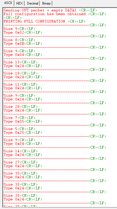
PrintStr("Full configuration has been obtained.\r\n");
}
}
First USBD_GetConfigurationDescriptorBegin is called with parameter value 4 to obtain total configuration size (first 4 bytes are only needed for that - the value itself is in last 2 bytes), second USBD_GetConfigurationDescriptorBegin is called with parameter value 587 (in my case) to get full configuration. Once we've got it, message "Full configuration has been obtained." is shown.
Build, upload and here is the output:

All 10 transactions are clearly seen in the program output.
Showing configuration in human readable format
Iterating through descriptors
As you might notice descriptors have several things in common, they follow the same structure: first field is bLength and second field is bDescriptorType. Using bLength we can slice data into portions and using bDescriptorType we can determine what an individual portion is. Each portion is a certain descriptor. Descriptor types can be found in USB documentation for standard descriptors and in UVC documentation for video class specific type descriptors. Class specific descriptors will have a third field that clarifies its type further (I'll get to it later).
The iteration function looks like this:
void USBD_ParseFullConfigurationDescriptor(uint8_t *ptrBuffer, uint16_t BufferSize)
{
    uint16_t CurrentPosition = 0;

    PrintStr("\r\nPRINTING FULL CONFIGURATION.\r\n");
    while(BufferSize - CurrentPosition)
    {
        PrintStr("------------------------------------\r\n");
        PrintStr("Size:");
        PrintDEC(ptrBuffer[CurrentPosition]);
        PrintStr("\r\n");
        PrintStr("Type:");
        PrintHEX(&ptrBuffer[CurrentPosition + 1], 1);
        PrintStr("\r\n");

        CurrentPosition += ptrBuffer[CurrentPosition];
    }
}
Output is:
My camera returns 46 descriptors. First type is 0x02 which is configuration descriptor, I shown its structure at the beginning of the article. To print it I'll create a function:
void PrintConfigurationDescriptor(uint8_t* ptrBuffer)
{
    uint16_t Temp16;

    PrintStr("Configuration descriptor:\r\n");
    PrintStr("bLength:\t\t\t");
    PrintDEC(ptrBuffer[0]);
    PrintStr("\r\n");
    PrintStr("bDescriptorType:\t\t");
    PrintHEX(&ptrBuffer[1], 1);
    PrintStr("\r\n");
    PrintStr("wTotalLength:\t\t\t");
    Temp16 = ptrBuffer[3] << 8;
    Temp16 |= ptrBuffer[2];
    PrintDEC(Temp16);
    PrintStr("\r\n");
    PrintStr("bNumInterfaces:\t\t");
    PrintDEC(ptrBuffer[4]);
    PrintStr("\r\n");
    PrintStr("bConfigurationValue:\t");
    PrintDEC(ptrBuffer[5]);
    PrintStr("\r\n");
    PrintStr("iConfiguration:\t\t");
    PrintDEC(ptrBuffer[6]);
    PrintStr("\r\n");
    PrintStr("bmAttributes:\t\t\t");
    PrintBIN8(ptrBuffer[7]);
    PrintStr("\r\n");
    PrintStr("bMaxPower:\t\t\t");
    PrintDEC(ptrBuffer[8]);
    PrintStr("\r\n");
}
And configuration parsing function is changed to:
void USBD_ParseFullConfigurationDescriptor(uint8_t *ptrBuffer, uint16_t BufferSize)
{
    uint16_t CurrentPosition = 0;

    PrintStr("\r\nPRINTING FULL CONFIGURATION.\r\n");
    while(BufferSize - CurrentPosition)
    {
        PrintStr("-------------------------------------\r\n");
        switch(ptrBuffer[CurrentPosition + 1])
        {
            case 0x02:
                PrintConfigurationDescriptor(ptrBuffer + CurrentPosition);
                break;
            default:
                PrintStr("Size:");
                PrintDEC(ptrBuffer[CurrentPosition]);
                PrintStr("\r\n");
                PrintStr("Type:");
                PrintHEX(&ptrBuffer[CurrentPosition + 1], 1);
                PrintStr("\r\n");
                break;
        }
        CurrentPosition += ptrBuffer[CurrentPosition];
    }
}
I added switch statement and print descriptor function call into case section. This pattern will be used for all descriptors.
NOTE: I will not show other PrintXXXDescriptor functions code inside this article as it similar to one in PrintConfigurationDescriptor function - just a combination of PrintStr-PrintDEC-PrintHEX-PrintBIN functions. You can always see them in source code.
Configuration descriptor
Program output is:
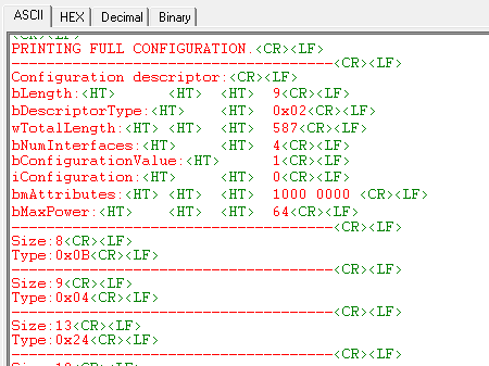
We've already discussed first three fields.
bNumInterfaces shows us that this configuration has 4 interfaces, each interface has its own purpose (I'll get to it later). Other important note here is that endpoints belong to an interface, each interface can have zero or more endpoints.
bConfigurationValue is the value I'll use to activate this configuration. According to USB specification there are one or more configurations in a device, but only one of them can be active at a time. So this value is passed as a parameter of a command that activates configuration.
iConfiguration is not used
bmAttributes in this case shows that a device can only be powered from USB port as opposite to self-powered (from outside power source or battery).
bMaxPower is in 2mA units. So this device has maximum consumption 128mA which is good because I can use power from Arduino Due without any problems.
Standard interface association descriptor
Next type is 0x0B which is Standard interface association descriptor. As we saw previous descriptor returned information that a device has 4 interfaces. If a device for example has video and audio functions, how to know which interfaces belong to which function? This descriptor gives an answer to this question. It shows first and last interface number that belong to specific function (class), then all its descriptors follow until next Standard interface association descriptor is reached that indicates start of the next function (class) descriptor section.
Here is the structure from USB specification:

Changes to parsing function switch statement:
//...

case 0x02:
        PrintConfigurationDescriptor(ptrBuffer + CurrentPosition);
        break;
 case 0x0B:
        PrintInterfaceAssociationDescriptor(ptrBuffer + CurrentPosition);
        break;

//...
Program output is:

Two encounters of interface association descriptor occurred: one immediately after configuration descriptor and one towards the end. That means that my device has two functions, codes of which are specified in bFunctionClass field.
First one has code 0x0E which is Video class (bingo!!! that is what I was looking for), second one is 0x01 which is audio class.
First class (video function) has two interfaces (bInterfaceCount = 2), first interface number is 0 and second is 1. bFunctionSubClass is 0x03 which means that this is Collection of video interfaces, bFunctionProtocol must be 0.
Second class (audio function) has also two interfaces, but first interface number is 2 and second is 3.
As audio function discussion is not part of this series of articles, I will not show its descriptors. For that I return from the parsing function once bFunctionClass other than 0x0E occurs:
//...

case 0x02:
        PrintConfigurationDescriptor(ptrBuffer + CurrentPosition);
        break;
case 0x0B:
        if(0x0E != ptrBuffer[CurrentPosition + 4])
            return;
        PrintInterfaceAssociationDescriptor(ptrBuffer + CurrentPosition);
        break;

//...
This shortens descriptors output to only video related ones. Was 46, became 34 thus 12 descriptors belong to audio function.
Standard Interface descriptor
Next type is 0x04 which is Standard interface descriptor [2, p.268]. Endpoints reside inside interfaces, each interface has its own role. As previous descriptor returns information that there are two interfaces number 0 and number 1 in video function, thus we should see two. Here is its structure from USB specification:

Changes to parsing function switch statement:
//...

case 0x02:
        PrintConfigurationDescriptor(ptrBuffer + CurrentPosition);
        break;
case 0x04:
        PrintInterfaceDescriptor(ptrBuffer + CurrentPosition);
        break;
case 0x0B:
        if(0x0E != ptrBuffer[CurrentPosition + 4])
            return;
        PrintInterfaceAssociationDescriptor(ptrBuffer + CurrentPosition);
        break;

//...
Program output is:

Output clearly shows two interfaces (roles) of video function: interface number 0 and number 1 (field bInterfaceNumber).
Please note field bAlternateSetting which is 0 here. Zero means it is interface, if it is not zero - this is different setting of this interface. It will be better understood once it outputs endpoint descriptors and I will explicitly return to this subject again.
Interface number 0 has one endpoint, interface number 1 has none endpoints (field bNumEndpoints) and I'll explain why former has no endpoints later.
Both interfaces have bInterfaceClass set to 0x0E which means they belong to Video class.
First interface plays Video Control role (field bInterfaceSubClass set to 0x01), second plays Video Streaming role (0x02). Another bingo!!!
bInterfaceProtocol must be set to 0.
Next important detail to notice is descriptor types that follow those two interface descriptors, they all have code 0x24 which means Video class-specific descriptor types. Till now we only dealt with standard descriptors and never with class-specific ones. They also follow the same pattern - first field is length, second is type. But type will only give us affiliation with video class and nothing else, therefore class-specific descriptors have third common field - SubType.
Further complication is that SubType is unique only within Video Control or Video Streaming subclass. For example code 0x01 means one thing in Video Control subclass and totally different thing in Video Streaming subclass, thus its parsing should be context sensitive. All descriptors with type 0x24 that follow Video Control interface descriptor must be parsed in one way, all descriptors with type 0x24 that follow Video Streaming interface must be parsed in another way. To do that I'll introduce additional variable Is_VS_Descriptors which has values "false" until code reaches Video Streaming interface descriptor. Then if code finds type 0x24, it redirects to appropriate parsing function:
void USBD_ParseFullConfigurationDescriptor(uint8_t *ptrBuffer, uint16_t BufferSize)
{
    uint16_t CurrentPosition = 0;
    uint32_t Is_VS_Descriptors = 0;

    PrintStr("\r\nPRINTING FULL CONFIGURATION.\r\n");
    while(BufferSize - CurrentPosition)
    {
        PrintStr("-------------------------------------\r\n");
        switch(ptrBuffer[CurrentPosition + 1])
        {
            case 0x02:
                PrintConfigurationDescriptor(ptrBuffer + CurrentPosition);
                break;
            case 0x04:
                PrintInterfaceDescriptor(ptrBuffer + CurrentPosition, &Is_VS_Descriptors);
                break;
//...
and PrintInterfaceDescriptor is changed to:
void PrintInterfaceDescriptor(uint8_t* ptrBuffer, uint32_t* Is_VS_Descriptors)
{
    //Set if SubClass is Video Streaming (0x02)
    if(0x02 == ptrBuffer[6])
        *Is_VS_Descriptors = 1;

 //...
Interface alternate settings
Standard interface descriptor describes not only itself but also interface alternate settings. Running the code so far returns not only those two interface descriptors that I shown before but also many alternate settings descriptors. Only difference is that bAlternateSetting is not zero. Usually an endpoint follows interface alternate setting descriptor that describes what exactly is different in a particular alternate setting from others.
Here shown three last alternate settings of Video Streaming interface (they are at the very end of program output):

Video control descriptors parsing
To parse Video control descriptors I'll add separate function with its own switch statement and call it from switch statement of main parsing function:
//...

case 0x24:                                    //Class-Specific interface
    if(!Is_VS_Descriptors)                    //Video Control (VC) descriptors
        USBD_ParseVCDescriptors(ptrBuffer + CurrentPosition)
    break;

//...
and
void USBD_ParseVCDescriptors(uint8_t* ptrBuffer)
{
    switch(ptrBuffer[2])
    {
        default:
            PrintStr("Size:");
            PrintDEC(ptrBuffer[0]);
            PrintStr("\r\n");
            PrintStr("Type:");
            PrintHEX(&ptrBuffer[1], 1);
            PrintStr("\r\n");
            PrintStr("SubType:");
            PrintHEX(&ptrBuffer[2], 1);
            PrintStr("\r\n");
            break;
    }
}
Program output is:

There are subtypes: 0x01, 0x02, 0x03 and 0x06 in VC subclass section.
Name of those descriptors are: VC Header, VC Input Terminal, VC Output Terminal, VC Extension Unit.
VC Header descriptor
Amongst other information this descriptor shows which Video Streaming interfaces belong to this Video Control interface. As already known from the article my camera has only one Video Streaming interface therefore one VS interface number should be mentioned here. According to UVC specification [3, p.49] descriptor structure is:

Changes to VC parsing function:
//...

switch(ptrBuffer[2])
{
    case 0x01:
        PrintVCHeaderDescriptor(ptrBuffer);
        break;
    default:
        PrintStr("Size:");
        PrintDEC(ptrBuffer[0]);
        PrintStr("\r\n");
        PrintStr("Type:");
        PrintHEX(&ptrBuffer[1], 1);
        PrintStr("\r\n");
        PrintStr("SubType:");
        PrintHEX(&ptrBuffer[2], 1);
        PrintStr("\r\n");
        break;
}

//...
Program output is:

First thing to see is that this device's video function complies with 1.0 version (field bcdUVC). It was hard to find it and finally I found that specification version on some Linux forum where folks discuss driver writing topics. I compared it with version 1.1 that is easy to download from USB web-site and found really few differences which I'll state when I'm there. Anyway I did upload UVC specification 1.0 in very first article as a reference.
Only one Video Streaming interface belongs to this Video Control interface (field bInCollection), and mentioned Video Streaming interface has number 1 (field baInterfaceNr). This perfectly corresponds with what was found previously in Standard Interface Descriptor section.
VC Input terminal descriptor
Next subtype is 0x02 which is VC Input terminal descriptor [3, p52]. Here it means camera sensor unit and this descriptor gives an information about support of various video sensor controls like focus, exposure, etc. Also as it is the descriptor of physical unit of a camera, it has unique ID, all unit descriptors have it and additionally have ID(s) of unit(s) to which they connected. I'll use this information to build device diagram.
Descriptor structure according to UVC specification:

Changes to VC parsing function:
//...

case 0x01:
    PrintVCHeaderDescriptor(ptrBuffer);
    break;
case 0x02:
    PrintVCInputTerminalDescriptor(ptrBuffer);
    break;
default:
    PrintStr("Size:");
    PrintDEC(ptrBuffer[0]);
    PrintStr("\r\n");
    PrintStr("Type:");
    PrintHEX(&ptrBuffer[1], 1);
    PrintStr("\r\n");
    PrintStr("SubType:");
    PrintHEX(&ptrBuffer[2], 1);
    PrintStr("\r\n");
    break;

//...
Program output is:

Unique ID is 1 (field bTerminalID), type of this unit is 0x0201 (field wTerminalType) which is "Camera sensor" [3, Appendix B]. It is not connected to other units (bAssocTerminal is 0) and this is because sensor is the first unit in a device, other units will be connected to it instead. Optical zoom is not supported by my camera therefore all three xxxFocalxxx fields are zero. Controls occupy three bytes (field bControlSize): auto-exposure mode and exposure time - bits 1 and 3 (very cheap camera!).
VC Processing unit descriptor
Next subtype is 0x05 which is VC Processing unit descriptor [3, p.55]. This descriptor exposes more controls related to image correction and digital multiplier.
Descriptor structure according to UVC specification:

Note: if your camera adheres to 1.1 version, there will be one additional bitmap (1 byte) field bmVideoStandards right after iProcessing field.
Changes to VC parsing function:
//...

case 0x02:
    PrintVCInputTerminalDescriptor(ptrBuffer);
    break;
case 0x05:
    PrintVCProcessingUnitDescriptor(ptrBuffer);
    break;
default:
    PrintStr("Size:");
    PrintDEC(ptrBuffer[0]);
    PrintStr("\r\n");
    PrintStr("Type:");
    PrintHEX(&ptrBuffer[1], 1);
    PrintStr("\r\n");
    PrintStr("SubType:");
    PrintHEX(&ptrBuffer[2], 1);
    PrintStr("\r\n");
    break;

//...
Program output is:

Unique ID is 2 (field bUnitId), it is connected to camera sensor (field bSourceID is 1), does not have digital multiplier (field wMaxMultiplier), controls occupy 2 bytes (field bControlSize) and has contrast, backlight compensation, gain, etc.
VC Output terminal descriptor
Next subtype is 0x03 which is VC Output terminal descriptor [3, p.51]. As stated in the name of the descriptor it should tell us information about device output, in our case about USB-output.
Descriptor structure according to UVC specification:

Changes to VC parsing function:
//...

case 0x02:
    PrintVCInputTerminalDescriptor(ptrBuffer);
    break;
case 0x03:
    PrintVCOutputTerminalDescriptor(ptrBuffer);
    break;
case 0x05:
    PrintVCProcessingUnitDescriptor(ptrBuffer);
    break;
//...
Program output is:

Unique ID is 3 (field bTerminalID), terminal type is 0x0101 (field wTerminalType) which is "A Terminal dealing with a signal carried over an endpoint in a VideoStreaming interface" [3, p.117]. Output terminal is connected to processing unit (field bSourceID).
VC Extension unit descriptor
Next subtype (and last for VC descriptors) is 0x06 which is VC Extension unit descriptor [3, p.56]. Extension unit descriptor gives generic USB-driver on the computer information about what vendor-specific driver to use to handle a device. To understand the information in this descriptor, one must have deep knowledge about a specific camera (like to be a part of development team that made it). I'll print it anyway to show how vendor-specific information is given, it might be interesting to somebody.
Descriptor structure according to UVC specification:

Changes to VC parsing function:
//...

case 0x05:
    PrintVCProcessingUnitDescriptor(ptrBuffer);
    break;
case 0x06:
    PrintVCExtensionUnitDescriptor(ptrBuffer);
    break;
default:
    PrintStr("Size:");
    PrintDEC(ptrBuffer[0]);
    PrintStr("\r\n");
    PrintStr("Type:");
    PrintHEX(&ptrBuffer[1], 1);
    PrintStr("\r\n");
    PrintStr("SubType:");
    PrintHEX(&ptrBuffer[2], 1);
    PrintStr("\r\n");
    break;

//...
Program output is:
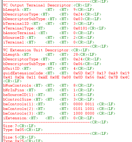
Unique ID is 4 (field bUnitID), GUID is in field guidExtensionCode that is used to identify vendor's driver, it has 8 controls that are controlled by vendor's driver (field bNumControls), connected to unit with ID 1 which is image sensor (input terminal) - fields bNrInPins and baSourceID. Controls (known by vendor's driver) that are used by this device are marked as 1 but what are those controls is known by vendor's driver only as such information is not disclosed in the descriptor.
Note that GUID is shown here in a way it is stored - just a sequence of bytes. To see it like it's shown in an operation system, you need to find online GUID converter and paste string 5DC717A91941DA11AE0E000D56AC7B4C (0x and spaces removed) into it and get {A917C75D-4119-11DA-AE0E-000D56AC7B4C}.
Standard endpoint descriptor
Next descriptor is standard descriptor with type 0x05 which is standard endpoint descriptor [2, p.269]. It gives us information we need to create communication pipes such is endpoint address, type, direction, transfer maximum size and interval. On the screenshot above there is one endpoint that is located inside Video Control (VC) section, there also one endpoint under each alternate setting in Video Streaming (VS) section (see Interface alternate settings section). Thus the endpoint that is in VC is used to changed controls like focus, exposure, multiplication, contrast, etc., and one of the endpoints in VS section is used for streaming. You will see that they (endpoints in VS section) have the same parameters except maximum transfer size and transactions quantity in one micro-frame that is how bandwidth is controlled. Default VS interface does not have endpoint which makes no streaming after device initialized, and only after one of the alternate setting is selected (there is special standard command for that), a stream starts with parameters of selected alternate setting's endpoint.
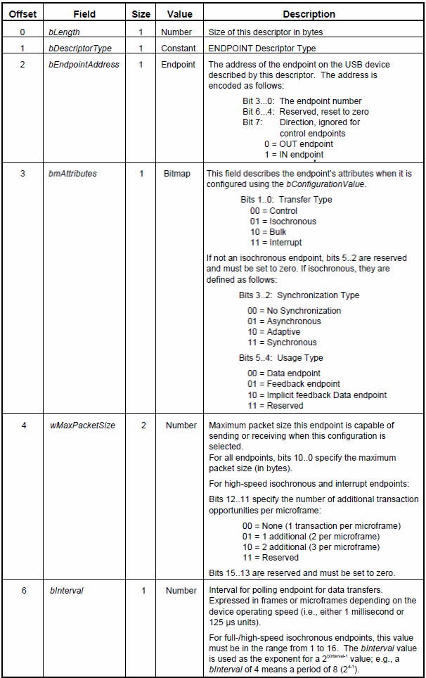
Descriptor structure according to USB specification:
Changes to main parsing function:
//...

case 0x04:
    PrintInterfaceDescriptor(ptrBuffer + CurrentPosition, &Is_VS_Descriptors);
    break;
case 0x05:
    PrintEndpointDescriptor(ptrBuffer + CurrentPosition);
    break;
case 0x0B:
    if(0x0E != ptrBuffer[CurrentPosition + 4])
        return;
    PrintInterfaceAssociationDescriptor(ptrBuffer + CurrentPosition);
    break;

//...
Program output is:
 There is one endpoint inside Video Control section and seven inside Video Streaming section of my camera (although only three are shown on screenshot to not make it too long).
Video Control endpoint is interrupt endpoint (bits 1..0 = 11, field bmAttributes), direction is IN (bit 7 = 1, field bEndpoitAddress), endpoint number is 1 (bit 0...3, field bEndpoitAddress), maximum transfer size is 10 (bits 10...0 = 1010, field wMaxPacketSize). This endpoint must be polled every 2^(5-1)=16th micro-frame (field bInterval).
According to Video Class specification [3, p.39], such an endpoint is used to report completion of some operations like changing focus, brightness, contrast, etc. if that operation takes more than 10ms to proceed. I will not use it in this article.
More interesting are those endpoints that belong to Video Streaming section. Each of them is located under interface alternate setting descriptor which means activating alternate setting will apply values of an endpoint that is right under it.
Let's see what is similar and different in streaming endpoints. Similarities are: they all isochronous (output is periodic - other word for stream), they all IN (from device to host), they all have number (address) - 2. Differences: max packet size is 128, 512 and 1024 bytes (on screenshot), but there are some with 768 bytes that is not shown. Another is the number of additional transactions in the micro-frame, on the screenshot there is only value zero (bits 12..11 of field wMaxPacketSize) that means 1 transaction per micro-frame, but my camera also has two settings with 2 transactions per micro-frame with sizes 768 and 1024 bytes and two settings with 3 transactions per micro-frame with sizes 768 and 1024 bytes of packet sizes.
Now you can easily see how bandwidth can be changed depending on host capabilities. As this article is about Arduino Due, so I'll attempt to use the lowest settings possible at first and then move up until it cannot process the stream anymore. I will not use settings with more than 1 transactions per micro-frame as this is too fast for Arduino Due. That leaves me three alternative settings to use: 1, 2 and 3 (all with one transaction per frame).
Class-specific interrupt endpoint descriptor
Next descriptor with type 0x25 is class-specific interrupt endpoint descriptor [3, p.58]. This descriptor is located right under VC standard endpoint descriptor and describes one thing only - maximum size to hold interrupt report. The need for it arises from the fact that standard endpoint descriptor gives the maximum transfer size only but if the structure that is sent is bigger than max transfer size - several transactions must be carried out and the whole structure is saved in a host's buffer with necessary size. This size is given by the descriptor.
Descriptor structure according to UVC specification:

Changes to main parsing function:
//...

case 0x24:                                    //Class-Specific interface
    if(!Is_VS_Descriptors)                    //Video Control (VC) descriptors
        USBD_ParseVCDescriptors(ptrBuffer + CurrentPosition);
    break;
case 0x25:
    PrintClassSpecificInterruptEndpointDescriptor(ptrBuffer + CurrentPosition);
    break;
default:
    PrintStr("Size:");
    PrintDEC(ptrBuffer[CurrentPosition]);
    PrintStr("\r\n");
    PrintStr("Type:");
    PrintHEX(&ptrBuffer[CurrentPosition + 1], 1);
    PrintStr("\r\n");
    break;

//...
Program output is:

As can be seen host needs to provide 10 bytes buffer to store data from this interrupt endpoint.
Video streaming descriptors parsing
Last unparsed section is Video Streaming or VS descriptors. I'll process it the same way I did with Video Control descriptors - in its own parsing function with case statement inside:
void USBD_ParseVSDescriptors(uint8_t* ptrBuffer)
{
    switch(ptrBuffer[2])
    {
        default:
            PrintStr("Size:");
            PrintDEC(ptrBuffer[0]);
            PrintStr("\r\n");
            PrintStr("Type:");
            PrintHEX(&ptrBuffer[1], 1);
            PrintStr("\r\n");
            PrintStr("SubType:");
            PrintHEX(&ptrBuffer[2], 1);
            PrintStr("\r\n");
            break;
    }
}
and it is called from main parsing function:
//...

case 0x24:                                    //Class-Specific interface
    if(!Is_VS_Descriptors)                    //Video Control (VC) descriptors
        USBD_ParseVCDescriptors(ptrBuffer + CurrentPosition);
    else                                      //Video Streaming (VS) descriptors
        USBD_ParseVSDescriptors(ptrBuffer + CurrentPosition);
    break;

//...
Program output is:

There are VS descriptors of subtypes 0x01, 0x03, 0x04, 0x05 and 0x0D which are VS input header, VS still image frame, VS format uncompressed, VS frame uncompressed and VS colour format descriptors respectively. Understanding information in those descriptors gives us amongst other information video format and frame resolutions.
VS input header descriptor
VS input header descriptor gives overall information about video capabilities and formats [3, p.60]. According to UVC standard its structure is:

Changes to VS parsing function:
//...

case 0x01:
    PrintVSInputHeaderDescriptor(ptrBuffer);
    break;
default:
    PrintStr("Size:");
    PrintDEC(ptrBuffer[0]);
    PrintStr("\r\n");
    PrintStr("Type:");
    PrintHEX(&ptrBuffer[1], 1);
    PrintStr("\r\n");
    PrintStr("SubType:");
    PrintHEX(&ptrBuffer[2], 1);
    PrintStr("\r\n");
    break;

//...
Program output is:
 My camera has one only format (field bNumFormats).
Size of VS section is 223 bytes (field wTotalLength).
Streaming endpoint number is 2 (bits 0..1 of field bEndpointAddress) and it is IN endpoint (bit 7 is 1 of field bEndpointAddress).
My camera does not support dynamic format change (bit 0 of field bmInfo) which is logical as there is one format only available.
Streaming endpoint is connected to output terminal with ID 3 (field bTerminalLink) - see VC output terminal descriptor that was shown earlier in VC section.
There are 3 methods how to make photos with cameras. My camera uses method 2 (field bStillCaptureMethod). As this is not in a scope of this article, you can read more here [3, p.15]. The same is applied to next two fields: bTreggerSupport and bTriggerUsage.
To initiate stream, special structure should be sent to a device. This structure is filled with some information and bmControls(x) define which fields are supported. Bit 0 is 1, means wKeyFrameRate field should be sent to device (it will be more clear when discussion comes to sending that structure).
VS format uncompressed descriptor
Next subtype is 0x04 which is VS format uncompressed descriptor. Other formats can be: MJPEG, MPEG-1 SS, MPEG-1 PS, H.264, etc. It so happened that my camera format is uncompressed and this is good as I would not be able to de-compress stream if I had one of the compressed formats due to lack of power in Arduino Due for such operation. There is not even enough power to display uncompressed stream in colour, only in grey-scale. I think it would be possible to stream in colour if output was RGB as my 320x240 display requires it but camera gives YCbCr. To convert YCbCr to RGB some small (but critical for Arduino Due real time operation) calculations on each colour component should be performed thus I'll stream only Y-component as it represents brightness and gives grey-scale video.
Anyway, at this stage it is only known that format is uncompressed. How it is uncompressed is still to be understood from this descriptor.
According to Uncompressed Payload specification [4, p.4] descriptor structure is:

Changes to VS parsing function:
//...

case 0x01:
    PrintVSInputHeaderDescriptor(ptrBuffer);
    break;
case 0x04:
    PrintVSUncompressedVideoFormatDescriptor(ptrBuffer);
    break;
default:
    PrintStr("Size:");
    PrintDEC(ptrBuffer[0]);
    PrintStr("\r\n");
    PrintStr("Type:");
    PrintHEX(&ptrBuffer[1], 1);
    PrintStr("\r\n");
    PrintStr("SubType:");
    PrintHEX(&ptrBuffer[2], 1);
    PrintStr("\r\n");
    break;

//...
Program output is:
 Index of this format descriptor is 1 (field bFormatIndex). In my camera there is one and only format descriptor because it can stream in one format only.
It can stream in five different resolutions (field bNumFrameDescriptors is 5) and I can see that 5 descriptors with subtype 0x05 follow this descriptor - they will define frame resolutions.
If I take GUID 5955593200001000800000AA00389B71 (field guidFormat) and insert it into online guid converter, I'll get: {32595559-0000-0010-8000-00AA00389B71}. Googling it gives me format - YUY2. Only at this moment it is known how to handle the stream data!!!
This format uses 16 bits to present one pixel (field bBitsPerPixel). You can google YUY2 format and see that is it true.
As YUY2 is not interlaced format, all related fields are zero. Also, duplication of this stream is not restricted (field bCopyProtect) - whatever this means.
VS frame uncompressed descriptors
Next subtype is 0x05 which is VS frame uncompressed descriptor. Each format has several supported frame sizes, those are listed with help of VS frame descriptors that immediately follow VS format descriptor.
According to Uncompressed Payload specification [4, p.6] descriptor structure is:

Changes to VS parsing function:
//...
case 0x04:
    PrintVSUncompressedVideoFormatDescriptor(ptrBuffer);
    break;
case 0x05:
    PrintVSUncompressedVideoFrameDescriptor(ptrBuffer);
    break;
default:
    PrintStr("Size:");
    PrintDEC(ptrBuffer[0]);
    PrintStr("\r\n");
    PrintStr("Type:");
    PrintHEX(&ptrBuffer[1], 1);
    PrintStr("\r\n");
    PrintStr("SubType:");
    PrintHEX(&ptrBuffer[2], 1);
    PrintStr("\r\n");
    break;
//...
Program output is:

Frame sizes (only 3 of 5 are shown) can easily be seen: 160x120, 176x144, 320x240, (not shown here) 352x288 and 640x480. My TFT shield screen has resolution 320x240 so it would be nice to get stream with frame #3. Buffer for storing the whole frame is also shown here and it can be easily calculated. For example for 160x120 resolution: 160*120 = 19200 pixels, each pixel coded with 2 bytes in YUY2: 19200 * 2 = 38400 which you can see in field dwMaxVideoFrameBufferSize. Value in bFrameIndex will be used to specify resolution for streaming. Intervals specified here are all in 100ns units, for example 333333 means 333333*100 = 33333300ns = 0.033s which is 30 frames per second.
VS still image frame descriptor
Next subtype is 0x03 which is VS still image frame descriptor [3, p.64]. It defines how to make photos by a camera and I'll not do this, I only show it to complete reading all the descriptors to give a reader of this article some general understanding of what else is there.
According to UVC standard its structure is:

Changes to VS parsing function:
//...

case 0x01:
    PrintVSInputHeaderDescriptor(ptrBuffer);
    break;
case 0x03:
    PrintVSStillImageFrameDescriptor(ptrBuffer);
    break;
case 0x04:
    PrintVSUncompressedVideoFormatDescriptor(ptrBuffer);
    break;

//...
Program output is:

As can be seen there are 5 photo sizes that correspond with frame sizes shown in previous descriptor. My camera gives uncompressed stream thus bNumCompressionPatterns is zero.
VS color matching descriptor
Next and the last unshown descriptor's subtype is 0x0D which is VS colour matching descriptor [3, p.65]. It describes colour profile and I'll not use it too.
According to UVC standard its structure is:

Changes to VS parsing function:
//...

case 0x05:
    PrintVSUncompressedVideoFrameDescriptor(ptrBuffer);
    break;
case 0x0D:
    PrintVSColorMatchingDescriptors(ptrBuffer);
    break;
default:
    PrintStr("Size:");
    PrintDEC(ptrBuffer[0]);
    PrintStr("\r\n");
    PrintStr("Type:");
    PrintHEX(&ptrBuffer[1], 1);
    PrintStr("\r\n");
    PrintStr("SubType:");
    PrintHEX(&ptrBuffer[2], 1);
    PrintStr("\r\n");
    break;

//...
Program output is:
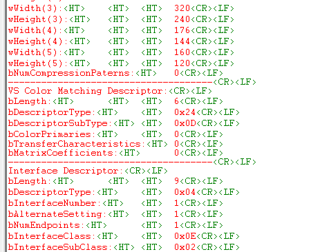
All values are zero which means "unspecified" so it does not provide much information at all and according to UVC specification this descriptor is optional.
Summarizing obtained information
After all necessary information has been obtained, it's time to group it together into some sort of visual representation so it can be easily used to complete USB device enumeration and video stream initiation:

Conclusion
At this moment everything is ready to finish USB camera enumeration process and initiate video stream.
Source code is here.
Part 7 is here.