
Data Modelling using ERD with Crow Foot Notation
4.87/5 (13 votes)
Architecting Data Structures
Introduction
In this article, I am going to show you architecting data structures using the data modelling technique Entity Relationship Diagram with Crow Foot Notation.
Background
There are many techniques that are in use among data architects for designing data models, such as Entity Relationship Diagram (ERD) and Data Matrix, etc. This article however will be demonstrating only the most widely used technique, which is ERD. In ERD, there is a wide range of notations used by data architects for denoting the relationship and cardinality between the data entities. Some of such notations are OMT, IDEF, Bachman, Chen, Martin, UML and Crow Foo , however, this article is intended for demonstrating Crow Foot Notation only.
Relationship and Cardinality/Multiplicity
The understanding of relationship and cardinality/multiplicity between entities are vital in modelling a database system. When it comes to relationship between entities, one of the following three relationships can exist between two entities.
- One to One
- One to Many
- Many to Many
Let me explain them with some examples.
- A car needs a tax disc (One to One)
- A car has four wheels (One to Many)
- A car can carry more than one person (One to Many)
- A driver is allowed to drive more than one car and a car can be driven by more than one driver (Many to Many).
One must understand the possible cardinality a table/entity can take in a relationship too. A cardinality is the number of rows a table can have in the relationship. As you may have noticed, I have used the terms table and entity interchangeably, and the reason for that is an entity eventually becomes a table in the database. We will see how in detail in the coming sections.
The possible cardinalities are:
- One and Only One
- One or Many
- Zero or One or Many
- Zero or One
In the relationships that we have mentioned in the relationship section, when we say a car can carry more than one person, then we know that a minimum of one person the car will carry, which is the driver. Also, it can carry many upto 5 or 7 or more depending on the vehicle. So we can now add further constraints - One to (One or Many). The one or many is called the cardinality/multiplicity in a relationship.
Let us see some more examples.
A car can have one and only one tax disc – One to (One and Only One)
A driver can drive more than one vehicle, but at the same time he doesn’t need to own a car and can use public transportation. In this instance, the driver drives zero vehicles – One to (Zero or One or Many).
A car can be declared off the road and doesn’t require a tax disc. In this instance, a car doesn't have a tax disc - One to (Zero or One).
A car owner or the owner’s spouse or any comprehensive licence holder can drive the owner’s car – (Many to One). Again, the car can be declared off road and no one can drive it – (Zero or One or Many) to One
You get the idea!
Crow Foot Notation Symbols
Now let us take a look at the crow foot notation symbols and understand their meaning before diving into datamodelling.
To illustrate the above relationship and cardinality of the entities in an ERD, the Crow Foot Notation Symbols are used with cardinality. The Crow Foot’s symbols and its meaning are given below. The symbols given in the parenthesis are used in UML.

I am sure that it is self-explanatory and does not require further explanation. However, if you have any questions, please do not hesitate to contact me by using the comments at the bottom of this article and I will be more than happy to help you.
Data Models
There are three levels of data models involved in the data modelling process. The conceptual and logical levels of data model may undergo as many iterations as it can go until all entities and relationships are identified, finalised and agreed with all stakeholders. Then the final level of physical model is developed to create the database.
Now let’s take a look at the three levels of models:
- Conceptual Model
- Logical Model
- Physical Model
To demonstrate these three data models, I am going to use a short version of an Online Motor Insurance Quote System. The above three levels of a data model are executed in the same order as they are given.
Note: Please note that this model is not by any means a complete online motor quote system and for simplicity, I have ignored many data elements from the system like Payments and many others.
Conceptual Model
In this level, entities and its relationships are identified by engaging all the stakeholders involved in the project. When the requirement is ready, then the data architect creates the conceptual model by having discussions with business analysts, product owners and other stake holders. The conceptual model is an abstract form of logical model and it shows all entities at high level without worrying about the detailed structure such as attributes (columns) and its types.
The following entities and relationships are identified for our Online Motor Insurance Quote System.
Entities
UserQuoteVehicleDriverClaimConvictionPolicyMTAEndorsementDocument
Relationships & Cardinalities
- A User can have zero or one or many quotes. - One to (Zero or One or Many)
- A Quote can have only one vehicle (Multiple vehicles on a single policy are not supported by the insurers’ panel) – One to (One and Only One)
- A Quote can have one or many Drivers. (One to (One or Many)
- A Driver can have zero or one or many claims - One to (Zero or One or Many)
- A Driver can have zero or one or many convictions - One to (Zero or One or Many)
- A Quote can have zero or only one policy - One to (Zero or One)
- A Policy can have zero or one or many endorsements - One to (Zero or One or Many)
- A Policy can have zero or one or many MTA. One to (Zero or One or Many)
A document can be part of one or many policies and a policy can have one or many documents. (One or Many) to (One or Many)
Until the conceptual model is agreed and signed off by the functional team, this process goes through many iterations. The conceptual model for the above requirement is shown below:

Things to note:
Dotted Lines means - Weak (Non-Identifying) Relationship
- Entity's existence is independent of other entities
- Primary Key of child entity doesn’t contain Primary Key of parent entity
Solid Lines means - Strong (Identifying) Relationship
- Child entity's existence is dependent on parent
- Primary Key of child entity contains Primary Key of parent entity
Logical Model
Once the conceptual model is accepted and signed off by the functional team, then the logical model helps to define the detailed structure of the entities and its relationships. The logical model forms the basis for the physical model. It is a very important level because this model clearly represents the business requirement and data structures that are required for the system.
By taking the findings from the conceptual model, the detailed structure of each entity is designed in the logical model. The attributes of the entities and its types are identified in this level however the types are platform independent. The actual table name and column names are not necessarily matching the entity name and attributes in the logical model.
For brevity, I have not included all attributes but in the real world, you will expect far more attributes. The reason being, this is to convey the concept of datamodelling and not providing a full fledged system as such.
The following diagram is the logical model for the relationships between entities for our system.
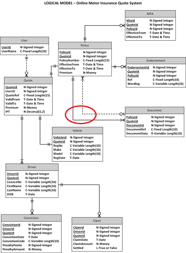
The logical model defines the attributes (columns) and its types (data types) for each entity but
it is still platform independent. It means by taking a logical model, one can implement in any
database of their choice such as Oracle or SQL Server.
Physical Model
The physical data model visually represents the actual database schema and it is platform specific. It means that the physical model can be implemented into the database which the model was designed for. For example, if a physical model is designed for SQL Server, then it cannot be implemented into ORACLE simply because the data structures are database specific and its columns' data types will work only on the targeted DB.
For example, in our example, the column types are generated targeting SQL SERVER (first diagram below) database. It means that the physical model need to be modified for other databases like Oracle (second diagram below). The reason for that is the data type VARCHAR in SQL SERVER physical model cannot be used in ORACLE as the data type is invalid.
This means that the physical model is the actual representation of the database model and one can create the actual database schema straight from the physical model and run into the DBMS directly by using a right tool. There are many tools out there to do the job.
Also the Many-to-Many relationship between Policy and Document has been implemented in the physical model by introducing a link table PolicyDocument. Remember that Many-to-Many relationship cannot be implemented without a link table for any two entities.
The table name, column names and the column data types for the target database are finalised in the physical model as shown below. The red circle is just to highlight that the actual implementation of Many-to-Many relationship has taken place in the physical model and nothing more than that.
I have generated two physical models from the same logical model without much work using a tool. The first one is for SQL SERVER and the second one for ORACLE.


We can also generate the SQL scripts for the targeted database from the tool but that is beyond scope of this article. Hope you find this article useful and I am more than happy to answer if you have any questions.
Please do not forget to vote for me if you find it useful. Thank you!