
[OoB] Shooting Paintball Marker with Relay, Arduino and .NET WinForms
How to shoot paintball marker with relay, Arduino and .NET Winforms
My first Arduino based project was Sonar with C#, JS and HTML5. Now I continue the "Out of Boredom" series with a setup that allows firing a paintball marker (gun) with a command sent from a computer. :) This time software stack is simpler - just a small Arduino sketch and uncomplicated WinForms (.NET/C#) application, but hardware requires a bit of electronics knowledge. Don't worry though, nothing too complicated - I'm definitely not an expert in this field...

The project is based around an electromechanical relay. Such relay is basically an electronically controlled switch that allows you to turn powerful devices on and off by sending a signal from Arduino's output pins. You can control very large motors or light bulbs for example. The beauty of this component is the fact that you can govern external circuits - there is no physical link between your control circuit and the thing you want to turn on/off. You can use a relay for devices that require huge current but you can also control more subtle equipment, and that's what I decided to do. I play paintball/speedball and I happen to own high-end electro-pneumatic marker called DM13. Such marker has electronically operated trigger and uses solenoid valve to shoot... I thought: "Wouldn't it be cool to press enter on my laptop and make this gun fire nearly 20 balls per second?"... See this video to see how it worked :)
This is a list of hardware parts used:
| Element | Role |
| Arduino Uno R3 | Controlling trigger via relay and communicating with PC |
| JZC-11F 005-IZ SPDT relay | Simulating trigger pull by closing trigger circuit |
| P2N2222AG NPN transistor | Supplying current to operate relay |
| 1.2k Ohm resistor | Limiting transistor base current |
| Green LED | Signalling ready state |
| Red LED | Signalling firing |
| 2x 330 Ohm resistor | Limiting current going through diodes |
| Piezo buzzer | Signalling read/fire with different tones |
| SPST switch | Turning buzzer on/off |
| Breadboard and jumper wires or universal board | Connecting components |
And this is the circuit diagram:
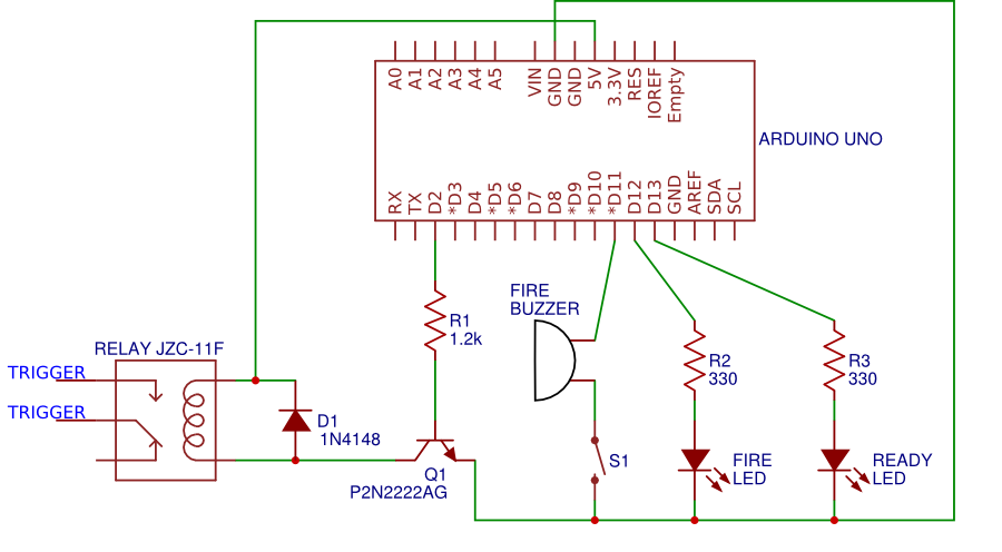
LED connected to Pin 13 is used to signal that device is ready, LED attached to Pin 12 indicates firing (closed trigger circuit). LEDs are of course not connected to Arduino directly, there are resistors protecting them from overcurrent. Buzzer is there to make one tone when device is ready and another (higher) tone when device is firing. The purpose of a switch is to make your life easier while testing. Buzzer sound can get annoying quickly so you can turn it off...
These are the boring bits, the more interesting stuff is on the left side of the diagram. Pin 2 is connected (via resistor) to a base of NPN transistor and collector is attached to relay coil. The transistor is needed because the coil, which controls the switching function, needs more power then Arduino output pins can supply. In this circuit transistor is used not as amplifier but as a switch. When Pin 2 is set to HIGH (base-emitter voltage = 5V), the transistor reaches its fully-on state and current flows through collector energizing the coil. Putting HIGH state on Pin 2 results in a connection between relay's COM (Common) and NO (Normally Open) pins. I've checked my marker with a multimeter (in resistance mode) and I was able to see that pulling the trigger resulted in a closed circuit between middle and lower pins of the trigger switch. Attaching one cable between middle pin of the switch and COM pin, and another cable between lower switch pin and Normally Open pin gives the ability to simulate trigger pull. In other words: HIGH state on Arduino's Pin 2 equals trigger pull as far as maker is concerned*. It's quite simple but as you've seen on the video it works really well! One more thing: look on the diagram on the right-hand side of JZC-11F relay - there's a signal diode and its purpose is to protect the transistor from voltage spikes that appear when Pin 2 to is put to LOW state (when supply voltage is removed from relay's coil). Such diode usage is called "flyback" or "freewheeling"... I first created this circuit on a breadboard and then soldered it on a universal board... Keep in mind that there are multiple Arduino relay shields available so you don't really have to create such transistor based circuit yourself. I did it because I think that it's a nice way to refresh some very basic electronics knowledge. Ok, we are done with hardware!
Now time for software (this GitHub repository contains all the code)!
Here's the complete Arduino sketch:
const byte fireRelayPin = 2;
const byte fireBuzzerPin = 11;
const byte fireLedPin = 12;
const byte readyLedPin = 13;

const byte readyToFireMessage = 6; // ASCII ACK
const byte fireCommand = 70; // ASCII F
const byte triggerPullDelayInMs = 30;
const byte fireBuzzerHz = 1000;
const byte readyBuzzerHz = 400;

void setup() {
    pinMode(fireRelayPin, OUTPUT);
    pinMode(fireBuzzerPin, OUTPUT);
    pinMode(fireLedPin, OUTPUT);
    pinMode(readyLedPin, OUTPUT);

    Serial.begin(9600);

    tone(fireBuzzerPin, readyBuzzerHz);
    digitalWrite(readyLedPin, HIGH);

    Serial.write(readyToFireMessage);
}

void loop() {
   if (Serial.available()) {
        byte data = Serial.read();

        if (data == fireCommand) {
            pullTrigger();
            delay(triggerPullDelayInMs);
            releaseTrigger();
        }
    }
}

void pullTrigger() {
    digitalWrite(fireLedPin, HIGH);
    digitalWrite(fireRelayPin, HIGH);
    tone(fireBuzzerPin, fireBuzzerHz);
}

void releaseTrigger() {
    digitalWrite(fireLedPin, LOW);
    digitalWrite(fireRelayPin, LOW);
    tone(fireBuzzerPin, readyBuzzerHz);

    Serial.write(readyToFireMessage);
}
Nothing complicated. :) First, the usual (good) practice of creating constants for pin numbers and other useful values. Then there is a setup method that configures pin modes, initializes serial connection (used to communicate with PC), and turns on the "ready" LED. There is also a call to tune function. tune is used to generate sound by making piezoelectric element in buzzer vibrate at a designated frequency. In loop function, the program waits for data sent by PC via serial port and checks if this data means a fire command (ASCII letter 'F'). If so, a trigger pull is simulated followed by a slight delay and trigger release. The digitalWrite(fireRelayPin, HIGH); line is what makes paintball gun fire. If you've looked carefully, you've noticed Serial.write(readyToFireMessage); calls in setup and releaseTrigger functions. These exist to let the computer know that Arduino is ready to receive first fire command or is ready to process a new one.
This is the .NET 4.5 WinForms application build to control paintball marker:

Pressing "Fire" button once makes the marker fire one shot, pressing and holding it makes it fire in a series. How many balls per second will be fired depends of course on triggerPullDelayInMs value, relay speed, marker settings (mine DM13 was setup in semi mode capped to around 20bps), paintball loader speed, etc. Shooting is only possible when "Device is ready to fire" shows "YES" and "Safe" checkbox is not ticked.
Here's the code behind the CommandWindow shown above (few particularly dull lines removed):
using System;
using System.Drawing;
using System.IO.Ports;
using System.Threading;
using System.Windows.Forms;

namespace PbFireApp
{
    public partial class CommandWindow : Form
    {
        private const byte ReadyToFireMessage = 6; // ASCII ACK
        private const byte FireCommand = 70; // ASCII F

        private bool _isReadyToFire;
        private bool IsReadyToFire
        {
            get
            {
                return _isReadyToFire;
            }
            set
            {
                _isReadyToFire = value;
                 SetIsReadyToFireLabel();
            }
        }

        public CommandWindow()
        {
            InitializeComponent();

            IsReadyToFire = false;
            spArduino.DataReceived += new SerialDataReceivedEventHandler(DataReceivedHandler);
        }

        private void DataReceivedHandler(object sender, SerialDataReceivedEventArgs e)
        {
            byte data = (byte)spArduino.ReadByte();
            IsReadyToFire = data == ReadyToFireMessage;
        }

        private void Fire()
        {
            if (!chkSafe.Checked && IsReadyToFire)
            {
                IsReadyToFire = false;
                spArduino.Write(new byte[] { FireCommand }, 0, 1);
            }
        }

        private void btnConnect_Click(object sender, EventArgs e)
        {
            try
            {
                if (spArduino.IsOpen)
                {
                    spArduino.Close();

                    btnConnect.Text = "Connect";
                    gbFire.Enabled = false;
                }
                else
                {
                    spArduino.BaudRate = (int)nudBaudRate.Value;
                    spArduino.PortName = txtPortName.Text;

                    spArduino.Open();

                    btnConnect.Text = "Disconnect";
                    gbFire.Enabled = true;
                }
            }
            catch (Exception ex)
            {
                MessageBox.Show(ex.ToString(),
                "Oh no :(", MessageBoxButtons.OK, MessageBoxIcon.Error);
            }
        }

        // ... more ...

        delegate void SetIsReadyToFireLabelCallback();

        private void SetIsReadyToFireLabel()
        {
            if (lblIsReadyToFire.InvokeRequired)
            {
                SetIsReadyToFireLabelCallback d =
                new SetIsReadyToFireLabelCallback(SetIsReadyToFireLabel);
                Invoke(d, new object[] { });
            }
            else
            {
                lblIsReadyToFire.Text = IsReadyToFire ? "YES" : "NO";
                lblIsReadyToFire.ForeColor = IsReadyToFire ? Color.Orange : Color.Black;
            }
        }
    }
}
The app is so simple that I decided to put all the code into form's cs file... SerialPort component is used to communicate with Arduino (I've written a bit more about serial communication in Sonar project posts). Paintball marker is instructed to fire when 'F' command (short for "Fire", ASCII code 70) is sent to Arduino. This line is responsible for it:
spArduino.Write(new byte[] { FireCommand }, 0, 1);
DataReceivedHandler method is used to set IsReadyToFire property to true when ACK (Acknowledge, ASCII 6) message is obtained from Arduino...
The code is quite obvious except for the SetIsReadyToFireLabel method. Why is it needed? The color and text of a Label control are changed when IsReadyToFire property is set. And that can happen when DataReceivedHandler is executed. We can't directly change UI elements from SerialPort.DataReceived event handler because this will result in an InvalidOperationException with a message such as this: "Cross-thread operation not valid: Control 'lblIsReadyToFire' accessed from a thread other than the thread it was created on.".
And that's it, second "Out of Boredom" project is complete. :)
1. It should be possible to control solenoid valve directly, but that would be more complicated and might result in damaging my precious DM13.…