
Converting .3ds Models to XAML Resources for a WPF 3D Scene
4.77/5 (15 votes)
Tutorial for converting 3D Studio model files (.3ds) to XAML resources for use in a WPF 3D living room scene
Introduction
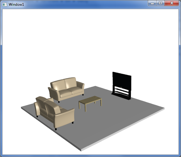
In this article, I will use the premise of creating a simple 3D scene (a living room with two couches, a coffee table and a TV) to cover:
- The basics of the scene: viewport, lights, floor and container for our furniture
- Hookup a virtual trackball so we can fully examine the scene
- Converting models from .3ds to XAML
- Massaging the XAML to be resource-ready
- Adding, sizing and positioning the models in the scene
Background
Two years ago, we started looking into using WPF for a 3D component of our application. I found a wealth of information on the WPF 3D basics (mostly using primitives), but had an exceedingly difficult time with one key point: how do you take a model created by a 3D artist and use it in WPF? At the time (and still true now for the most part), modelers are not creating your 3D assets in XAML – the 3D modelling tools seem to be slow in adopting XAML as a supported format. Back then, we were using DirectX for our 3D and most of our models were in .x format, but even much more ubiquitous formats such as .3ds have to be first converted to XAML before you can use them in WPF.
Today, if you do a search on how to convert from .3ds to XAML, you will find some helpful tools and examples, but even these fall short in my opinion due to the fact that every converter I've seen will export a scene to XAML, not a model. What’s the difference? A scene has a viewport, a camera, lights and one or more models. This is great if you want to create a 3D scene with just one 3D model. But what if you want to create a scene comprised of multiple 3D models? You don't want each model to come with its own viewport, camera and lights. And what if you want to use these models as a resource so you can have more than one in a scene? These are topics I will address in this article.
Step 1: Create the Project and Setup the Scene
The first step is to create a project to host our scene. There’s nothing special in this example and this is well-treaded ground in terms of WPF tutorials. Once you've created the project, we'll want to add the key elements of any WPF 3D scene: the viewport, the camera, and lights. Since this tutorial is more focused on the use of .3ds models as resources, I'm going to gloss over this step since this part of the setup is well covered in other articles. I've included a directional light and a spot light to add some reflective flare to the overall scene.
<Window x:Class="_3dsToXaml.Window1"
xmlns="http://schemas.microsoft.com/winfx/2006/xaml/presentation"
xmlns:x="http://schemas.microsoft.com/winfx/2006/xaml"
xmlns:inter3D="clr-namespace:_3DTools;assembly=3DTools"
Title="Window1" Height="500" Width="600"
x:Name="MainWindow">
<Grid>
<Viewport3D x:Name="viewport" RenderOptions.CachingHint="Cache" ClipToBounds="True" >
<Viewport3D.Camera>
<PerspectiveCamera x:Name="myPerspectiveCamera" FarPlaneDistance="300"
	LookDirection="0,0,-1" UpDirection="0,1,0" NearPlaneDistance="1"
	Position="0,3,25" FieldOfView="45">
<PerspectiveCamera.Transform>
<MatrixTransform3D>
</MatrixTransform3D>
</PerspectiveCamera.Transform>
</PerspectiveCamera>
</Viewport3D.Camera>

<ModelVisual3D x:Name="viewportLightsModelVisual3D">
<ModelVisual3D.Content>
<Model3DGroup>
<AmbientLight x:Name="ambientLight" Color="#666666"/>
<DirectionalLight x:Name="directionalLight" Color="#444444" Direction="0 -1 -1">
</DirectionalLight>
<SpotLight x:Name="spotLight" Color="#666666" Direction="0 0 -1"
	InnerConeAngle="30" OuterConeAngle="60" Position="0 1 30" >
</SpotLight>
</Model3DGroup>
</ModelVisual3D.Content>
</ModelVisual3D>
</Viewport3D>

</Grid>
</Window>
Running the project at this point is uninteresting because we haven't yet added anything to see! Since the scene we're creating will eventually be a living room, let’s go ahead and create a primitive to represent our floor.
<ModelUIElement3D x:Name="Floor" >
<GeometryModel3D>
<GeometryModel3D.Geometry>
<MeshGeometry3D x:Name="floorGeometry" Positions="{Binding FloorPoints3D,
	ElementName=MainWindow}" TriangleIndices="{Binding FloorPointsIndices,
	ElementName=MainWindow}" />
</GeometryModel3D.Geometry>
<GeometryModel3D.Material>
<MaterialGroup>
<DiffuseMaterial Brush="LightGray"/>
<SpecularMaterial Brush="LightGray" SpecularPower="100"/>
</MaterialGroup>
</GeometryModel3D.Material>
<GeometryModel3D.BackMaterial>
<DiffuseMaterial Brush="Black"/>
</GeometryModel3D.BackMaterial>
</GeometryModel3D>
</ModelUIElement3D>
You'll notice that the MeshGeometry3D Positions and TriangleIndices are obtained through binding. There’s no reason you couldn't just create these values inline within the XAML, but I find it easier to read/create these values in code (and hopefully it'll be easier for you to follow as well).
public Point3DCollection FloorPoints3D
{
get
{
double x = 6.0; // floor width / 2
double z = 6.0; // floor length / 2
double floorDepth = -0.2; // give the floor some depth so it's not a 2 dimensional plane

Point3DCollection points = new Point3DCollection(20);
Point3D point;
//top of the floor
point = new Point3D(-x, 0, z);// Floor Index - 0
points.Add(point);
point = new Point3D(x, 0, z);// Floor Index - 1
points.Add(point);
point = new Point3D(x, 0, -z);// Floor Index - 2
points.Add(point);
point = new Point3D(-x, 0, -z);// Floor Index - 3
points.Add(point);
//front side
point = new Point3D(-x, 0, z);// Floor Index - 4
points.Add(point);
point = new Point3D(-x, floorDepth, z);// Floor Index - 5
points.Add(point);
point = new Point3D(x, floorDepth, z);// Floor Index - 6
points.Add(point);
point = new Point3D(x, 0, z);// Floor Index - 7
points.Add(point);
//right side
point = new Point3D(x, 0, z);// Floor Index - 8
points.Add(point);
point = new Point3D(x, floorDepth, z);// Floor Index - 9
points.Add(point);
point = new Point3D(x, floorDepth, -z);// Floor Index - 10
points.Add(point);
point = new Point3D(x, 0, -z);// Floor Index - 11
points.Add(point);
//back side
point = new Point3D(x, 0, -z);// Floor Index - 12
points.Add(point);
point = new Point3D(x, floorDepth, -z);// Floor Index - 13
points.Add(point);
point = new Point3D(-x, floorDepth, -z);// Floor Index - 14
points.Add(point);
point = new Point3D(-x, 0, -z);// Floor Index - 15
points.Add(point);
//left side
point = new Point3D(-x, 0, -z);// Floor Index - 16
points.Add(point);
point = new Point3D(-x, floorDepth, -z);// Floor Index - 17
points.Add(point);
point = new Point3D(-x, floorDepth, z);// Floor Index - 18
points.Add(point);
point = new Point3D(-x, 0, z);// Floor Index - 19
points.Add(point);

return points;
}
}

public Int32Collection FloorPointsIndices
{
get
{
int[] indices = new int[] { 0, 1, 2, 0, 2, 3, 4, 5, 7, 5, 6, 7, 8, 9,
	11, 9, 10, 11, 12, 13, 15, 13, 14, 15, 16, 17, 19, 17, 18, 19 };
return new Int32Collection(indices);
}
}
If you run the project now, you'll have a 3D scene with just a floor – but you'll only get the current camera’s perspective of the floor. We want a way to move the camera so we can more fully explore the scene and see it from various angles. The most common way to do this is via a “virtual trackball”. Fortunately there’s a CodePlex project (3DTools) that makes adding a virtual trackball virtually painless.
xmlns:_3DTools ="clr-namespace:_3DTools;assembly=3DTools"
<_3DTools:TrackballDecorator Height="Auto">
<_3DTools:Interactive3DDecorator>
<Viewport3D … >
…
</Viewport3D>
</_3DTools:Interactive3DDecorator>
</_3DTools:TrackballDecorator>
The last part of Step 1 is to create a container to which we can add our furniture. We'll come back to this later.
<Window x:Class="_3dsToXaml.Window1"
xmlns="http://schemas.microsoft.com/winfx/2006/xaml/presentation"
xmlns:x="http://schemas.microsoft.com/winfx/2006/xaml"
xmlns:inter3D="clr-namespace:_3DTools;assembly=3DTools"
Title="Window1" Height="500" Width="600"
x:Name="MainWindow"

>
<Grid>
<inter3D:TrackballDecorator x:Name="inter3d" DockPanel.Dock="Bottom" Height="Auto">
<inter3D:Interactive3DDecorator>
<Viewport3D x:Name="viewport" RenderOptions.CachingHint="Cache" ClipToBounds="True" >
<Viewport3D.Camera>
…
</Viewport3D.Camera>

<ContainerUIElement3D x:Name="FurnitureContainer" />

<ModelUIElement3D x:Name="Floor" >
…
</ModelUIElement3D>

<ModelVisual3D x:Name="viewportLightsModelVisual3D">
…
</ModelVisual3D>
</Viewport3D>
</inter3D:Interactive3DDecorator>
</inter3D:TrackballDecorator>

</Grid>
</Window>
Step 2: Get Some [Free] Professional Models (.3ds) and Convert Them to XAML
Now we're ready to get some models for our scene. In this example, we'll be adding furniture models. There’s a wealth of free models available online and you can find a good list of sites to search here. I selected a couch, a coffee table, and a TV for our living room and I downloaded the models (in .3ds format) from here.
Once we've downloaded the models in .3ds format, we're ready to start converting them to XAML for use in our project. At the time of this writing, I'm aware of 3 different tools that will convert a .3ds model to XAML: Zam3D from Electric Rain, Deep Exploration from Right Hemisphere, and Viewer3ds written by Andrej Benedik. Depending on which tool you use, the model conversion process may vary slightly. For the purposes of this article, I will be using Zam3D -- it’s the tool I'm most familiar with and has a fully functional trial version available.
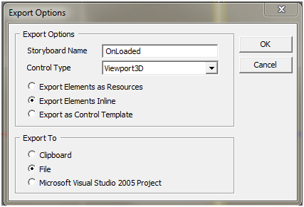
From Zam3D, select “New from 3DS…” from the file menu and find the .3ds model file you just downloaded (we'll start with the Sofa model). Next select “Export Scene to XAML…” from the file menu. Select Viewport3D as the Control Type and Export Elements Inline (see Step 2 Figure 1)
Step 3: Convert the XAML Models to Resources
We have now successfully converted a sofa model in .3ds to XAML, but the XAML is not quite ready for us to use. Why? Because, as I mentioned at the introduction of this article, the conversion process creates a scene (viewport, camera, lights and model) and we just want the model – we've already created the viewport, camera and lights for our scene. So we have to open the XAML file and manually remove these redundant elements so we're left with just the Model3Dgroup. Step 3 Figure 1 shows the unedited XAML and Step 3 Figure 2 shows what the XAML should look like once we've pruned it of the extraneous elements.
<Viewport3D x:Name="ZAM3DViewport3D" ClipToBounds="true" Width="400"
	Height="300" xmlns=http://schemas.microsoft.com/winfx/2006/xaml/presentation
	xmlns:x=http://schemas.microsoft.com/winfx/2006/xaml
	xmlns:d=http://schemas.microsoft.com/expression/interactivedesigner/2006
	xmlns:c=http://schemas.openxmlformats.org/markup-compatibility/2006
	c:Ignorable="d">
<Viewport3D.Camera>
<PerspectiveCamera x:Name="FrontOR7" FarPlaneDistance="460"
	LookDirection="0,0,-1" UpDirection="0,1,0" NearPlaneDistance="190"
	Position="-7.62939e-006,52.9203,328" FieldOfView="39.5978" />
</Viewport3D.Camera>

<ModelVisual3D>
<ModelVisual3D.Content>
<Model3DGroup x:Name="Scene"> <!-- Scene (XAML Path = ) -->
<Model3DGroup.Transform>
<Transform3DGroup>
<TranslateTransform3D OffsetX="0" OffsetY="0" OffsetZ="0"/>
<ScaleTransform3D ScaleX="1" ScaleY="1" ScaleZ="1"/>
<RotateTransform3D>
<RotateTransform3D.Rotation>
<AxisAngleRotation3D Angle="0" Axis="0 1 0"/>
</RotateTransform3D.Rotation>
</RotateTransform3D>
<TranslateTransform3D OffsetX="0" OffsetY="0" OffsetZ="0"/>
</Transform3DGroup>
</Model3DGroup.Transform>
<AmbientLight Color="#646464" />
<DirectionalLight Color="#FFFFFF" Direction="-0.612372,-0.5,-0.612372" />
<DirectionalLight Color="#FFFFFF" Direction="0.612372,-0.5,-0.612372" />
<Model3DGroup x:Name="Group01OR10">
<!—This is the main Model3Dgroup, we can remove everything around this -->
</Model3DGroup>
</Model3DGroup>
</ModelVisual3D.Content>
</ModelVisual3D>
</Viewport3D>
<Model3DGroup x:Name="Group01OR10">
<!—This is the main Model3Dgroup, we can remove everything around this -->
</Model3DGroup>
Now that we have the XAML file pruned down to just the Model3Delement, we're ready to convert it to a resource. By making it a resource, we accomplish:
- Separate the model XAML from the scene/window XAML
- We can re-use the model in the scene or other scenes without copy/paste
We will make the XAML file a usable resource dictionary by:
- Wrapping the
Model3DGroupXML with aResourceDictionaryelement - Naming the
Model3Dgroupresource with anx:Keyidentifier - Deleting all extraneous
x:Nameidentifiers in theModel3DGroupXAML
Steps a and b above are pretty straightforward and require no further explanation (see Step 3 Figure 3). Step c is necessary because Zam3D will name all of the child elements of our main Model3DGroup. Resources cannot be identified by Name, they must be identified by Key, but we don't need to reference any of these child elements directly so we can just remove all of these child Name attributes.*
*You can use Visual Studio to quickly remove all of these Name attributes. Use Find->Replace, for Find What enter x:Name=”*”, leave Replace with empty and under Find options, select Use:Wildcards.
<ResourceDictionary xmlns="http://schemas.microsoft.com/winfx/2006/xaml/presentation"
xmlns:x="http://schemas.microsoft.com/winfx/2006/xaml">
<Model3DGroup x:Key="sofa" >
<!— x:Name attributes have been removed from all child elements -->
</Model3DGroup>
</ResourceDictionary>
The last step in making our XAML model (ResourceDictionary) ready for use is to add it to our App.xaml so that it gets loaded during application startup (See Step 3 Figure 4).
<Application x:Class="_3dsToXaml.App"
xmlns="http://schemas.microsoft.com/winfx/2006/xaml/presentation"
xmlns:x="http://schemas.microsoft.com/winfx/2006/xaml"
StartupUri="Window1.xaml">
<Application.Resources>
<ResourceDictionary>
<ResourceDictionary.MergedDictionaries>
<ResourceDictionary Source="Models\sofa.xaml"/>
<ResourceDictionary Source="Models\table.xaml"/>
<ResourceDictionary Source="Models\tv.xaml"/>
</ResourceDictionary.MergedDictionaries>
</ResourceDictionary>
</Application.Resources>
</Application>
Step 4: Create a Base Class for the Models and Add Them to the Scene
In order to use our newly created model resources, we need a 3D element to display them. UIElement3D works well for this purpose. We can simply create a new UIElement3D object and set its VisualModel3D property to the contents of our resource. Since we'll be doing this for each model resource, I created a UIElement3D-derived class to encapsulate this functionality (see Step 4 Figure 1). Also included in the base class is the method “Move”, which we'll use to properly position our models once added to the scene (more on the Move method in Step 5).
class ModelBase : UIElement3D
{
public ModelBase(string resourceKey)
{
this.Visual3DModel = Application.Current.Resources[resourceKey] as Model3DGroup;
Debug.Assert(this.Visual3DModel != null);
}

public void Move(double offsetX, double offsetY, double offsetZ, double angle)
{
Transform3DGroup transform = new Transform3DGroup();
RotateTransform3D rotateTrans = new RotateTransform3D();
rotateTrans.Rotation = new AxisAngleRotation3D(new Vector3D(0, 1, 0), angle);
TranslateTransform3D translateTrans = new TranslateTransform3D(offsetX, offsetY, offsetZ);
transform.Children.Add(rotateTrans);
transform.Children.Add(translateTrans);
this.Transform = transform;
}
}
With our base class defined, adding models to the scene becomes pretty straight-forward. You'll recall in Step 1 that we created a ContainerUIElement3D in our main window XAML to house our furniture. To add models to the scene, all we need to do is create a ModelBase object and add it to the ContainerUIElement3D (Step 4 Figure 2).
private void CreateScene()
{
ModelBase sofa1 = new ModelBase("sofa");
this.FurnitureContainer.Children.Add(sofa1);

ModelBase sofa2 = new ModelBase("sofa");
this.FurnitureContainer.Children.Add(sofa2);

ModelBase table = new ModelBase("table");
this.FurnitureContainer.Children.Add(table);

ModelBase tv = new ModelBase("tv");
this.FurnitureContainer.Children.Add(tv);
}
We now have a scene with a floor, two sofas, a table, and a TV in it – a passable living room. However, we haven't moved the models into position yet. What’s worse is that we have no idea on the relative scale of these models. If we were to run the scene now, we would see a bunch of overlapping furniture in the middle of the floor of varying size. Time to cleanup and finish our scene.
Step 5: Model & Scene Cleanup
The first step in completing our living room scene is to scale the models so that their sizes make sense. So how big are the models? The answer is, it depends. In WPF 3D, all units are relative. Our sofa might appear to be enormous while the table is so small you can't even see it. It all depends on:
- What numbers the modeler used when creating the model
- What numbers we used when creating our viewport and camera
If we're obtaining models from various artists and have no prior knowledge of the coordinates before setting up our viewport and camera, chances are things will look way out of whack until we adjust the scale to something that looks reasonable. Fortunately the root Model3DGroup in the XAML for each of our models already has a Transform defined and a Transform3DGroup containing a ScaleTransform. To make the models appear the correct size, we need only experiment with various values for the x, y & z scale until we find the scale size that looks right (we'll want to scale uniformly lest we distort the model).
<ResourceDictionary xmlns="http://schemas.microsoft.com/winfx/2006/xaml/presentation"
xmlns:x="http://schemas.microsoft.com/winfx/2006/xaml">
<Model3DGroup x:Key="sofa" >
<Model3DGroup.Transform>
<Transform3DGroup>
<TranslateTransform3D OffsetX="0" OffsetY="0" OffsetZ="0"/>
<ScaleTransform3D ScaleX="0.023" ScaleY="0.023" ScaleZ="0.023"/>
<RotateTransform3D>
<RotateTransform3D.Rotation>
<AxisAngleRotation3D Angle="0" Axis="0 1 0"/>
</RotateTransform3D.Rotation>
</RotateTransform3D>
<TranslateTransform3D OffsetX="0" OffsetY="0" OffsetZ="0"/>
</Transform3DGroup>
</Model3DGroup.Transform>
…
</Model3DGroup x:Key="sofa" >
</ResourceDictionary>
Once properly scaled, the only thing left to do is to position the models on the floor so that they resemble a proper living room. We've already added a Move function in our ModelBase class that will take care of applying translate and rotate transforms (i.e. moving the model on the floor and spinning it to face the proper direction, respectively). Since we want all of our furniture to be on the floor and not floating in the sky or buried under ground, we need only concern ourselves with applying the proper x and z translations* as well as the proper rotation about the y axis.
* This assumes the model author created all components in positive y (i.e. the model origin is at the bottom of the model, not in the middle of it). Some models will be centered in y as well, in which case they'll need a y translation in order to appear to be resting on the floor.
private void CreateScene()
{
ModelBase sofa1 = new ModelBase("sofa");
this.FurnitureContainer.Children.Add(sofa1);//adds the first sofa to the middle of the floor
// move to the back edge of the floor
// This would be a -6 Z translation, but that would put the center
// of the sofa along the back edge.
// We want the back of the sofa along the back edge so we have to
// subtract half the depth of the sofa (roughly 1.2)
sofa1.Move(0, 0, -4.8, 0);

ModelBase sofa2 = new ModelBase("sofa");
this.FurnitureContainer.Children.Add(sofa2);//adds the second sofa to the middle of the floor
// rotate and move to the left edge of the floor
sofa2.Move(-4.8, 0, 0, 90);

ModelBase table = new ModelBase("table");
this.FurnitureContainer.Children.Add(table);

ModelBase tv = new ModelBase("tv");
this.FurnitureContainer.Children.Add(tv);
tv.Move(5.5, 0, 0, -90);
}
Conclusion
Congratulations on creating a fully functioning WPF 3D scene from .3ds files converted to XAML resources, complete with virtual trackball functionality. I hope you've found this article useful. If you haven't, please create a WPF 3D lake scene and go jump in it :)
History
- 3/2/2010 - First draft