
A TTGO Display T1 Based Fan Widget
5.00/5 (6 votes)
A project that allows you to use a knob to control a fan's RPM with feedback
Note: The GitHub version is a bit more advanced. I wanted to keep this demonstration simple.
Introduction
I wanted a little project to demonstrate some of my IoT ecosystem (htcw_*) that I have created, plus this just seemed like a fun little way to kill an hour or two.
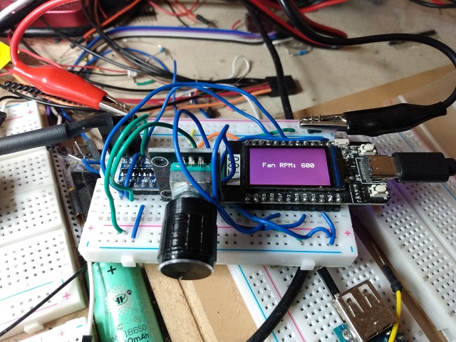
This project uses the nearly ubiquitous and venerable (at least among the ESP32 crowd) TTGO Display T1 because it's a nice little devkit with an integrated color display. It's easy to find, and relatively inexpensive for what it is. You can pick them up for as little as $12 plus shipping that I've found. It also uses a PWM based 4-pin fan like the kind you buy for a PC.
Prerequisites
- You'll need a 12V PWM based 4-pin fan - the kind with the tach feedback, and beware cheapo fans that use a fake tach that always reports the same RPM.
- You'll need a level shifter, probably. In theory you might be able to get away without one, but I recommend using it, and not running a circuit outside of its operating specs.
- You'll need a TTGO Display T1
- You'll need a 12V >= 0.2A power supply
- It helps to have some double ended male dupont connectors (long on both sides) to make connection points for the fan and 12V power supply alligator clips, though you can by with solid core wire maybe.
- You'll need one of those 2 line quadrature encoders that you can find for Arduino
- You'll need VS Code with the PlatformIO extension installed
- You'll need some patience to follow wiring.txt and wire the whole thing up. Do this carefully, because you're dealing with 12V and so if you wire it into anything other than the fan you'll fry stuff. I get extra antsy when sharing a ground, but it's okay for this circuit.
Understanding This Mess
There's not a lot to understand that I haven't covered previously in terms of technology, but here we're putting it all together. The only new thing I'm introducing is htcw_encoder which is pretty simple, and htcw_ttgo which simply makes it easier to use this particular devkit by pulling in all the integrated hardware support for you. It uses htcw_gfx for the display, including a True Type font I pulled from fontsquirrel.com and converted to a header file with my online utility.
When it starts up it will run the fan a bit to determine the maximum RPM it's capable of. When it's done it will stop the fan and you can twist the encoder knob clockwise (unless you reversed the pins!) to ramp up the RPM. It will then use adaptive RPM targeting to attempt to keep the fan at the same RPM you've indicated via the encoder knob. Keep in mind this doesn't work well for RPMs below the minimum effective rate, which varies fan to fan, but on mine is about 360 or so. It will try, but jitter at low RPMs.
You'll see feedback via the display on the fan's RPM. The tachs on these fans aren't perfect, so sometimes they momentarily spike a bit in terms of what they report, but otherwise it's straightforward.
Coding This Mess
There's not a lot to this due to the amount of menial furbling my ecosystem takes care of for you. The rest is pretty straightforward but we'll cover it anyway. All the meat is in one file.
main.cpp
First let's get the boilerplate stuff out of the way.
#define ENCODER_DATA 17
#define ENCODER_CLK 13
#define FAN_TACH 33
#define FAN_PWM 32
#define MAX_RPM NAN
#include <ttgo.hpp>
#include <encoder.hpp>
#include <fan_controller.hpp>
// downloaded from fontsquirrel.com and header generated with
// https://honeythecodewitch.com/gfx/generator
#include <fonts/Telegrama.hpp>
Here we're just making a few defines to keep things readable and more maintainable, and then we include the ttgo hardware support, the encoder support, the fan support, and finally the font we generated the header file for.
Next we declare the hardware that's external to the TTGO - the encoder and the fan:
static int_encoder<ENCODER_DATA,ENCODER_CLK,true> knob;
static fan_controller fan(
    [](uint16_t duty,void* state){ ledcWrite(0,duty>>8); },
    nullptr,
    FAN_TACH, MAX_RPM);
Here we're declaring the encoder that works on interrupts, and the fan controller, along with a flat lambda to handle the pulse with generation callback. We also pass in NAN for the fan max RPM so it will detect it, but you can change this.
The temporary string is just so we don't use valuable stack space when we need to format something.
static char tmpsz[256];
Finally we get to something non-trivial - drawing centered text on the screen:
static void draw_center_text(const char* text, int size=30) {
    draw::filled_rectangle(lcd,lcd.bounds(),color_t::purple);
    open_text_info oti;
    oti.font = &Telegrama;
    oti.text = text;
    oti.scale = oti.font->scale(size);
    oti.transparent_background = false;
    srect16 txtr = oti.font->measure_text(
        ssize16::max(),
        spoint16::zero(),
        oti.text,
        oti.scale).bounds();
    txtr.center_inplace((srect16)lcd.bounds());
    draw::text(lcd,txtr,oti,color_t::white,color_t::purple);
}
The first thing we're doing is clearing the screen by drawing a big purple filled_rectangle() to it that is the same bounds() as the lcd.
After that, we fill an open_text_info structure with our font and text information. The font is based on the name indicated on the generator tool when you made the file, and will typically be the same as the filename for the header, minus the extension. Note that it's a pointer to a font because a reference simply doesn't work in this instance.
Note the scale. The scale() routine converts a font size in pixel line height to a fractional percentage of the font's native height (which is big, so the number returned from scale() will be small)
We turn off the transparent_background (default on) for two reasons. The first is performance, as it takes time to alpha blend and thus anti-alias to a remote frame buffer, like that of the LCD. If you draw to a non-transparent background, you don't need to read back from the LCD. The second reason is more critical and very unfortunate. Espressif seems to have broken "SDA reads" in the latest Arduino framework implementations, such that they still kind of work, but are very slow and spill a bunch of "invalid pin selected" error messages to the serial port. The ST7789 display controller requires the use of SDA reads to do alpha blending and anti-aliasing so that creates a problem. Making the background non-transparent sidesteps this issue due to the above.
Now we measure_text(). The first parameter is the effective size of the text layout area. We just use the maximum value for an ssize16. The second parameter is an offset if any of the font layout - where it starts drawing. We use (0,0). The next parameter is the text to measure, and finally, we indicate the scale we're using for the font. We then take the ssize16 and convert it to a srect16 by taking its bounds().
Next, we center the rectangle by modifying its values in place and we do so based on the size of the display.
Finally, we draw the text() to the LCD, at the specified destination rectangle, with the struct we filled above, and with the foreground and background colors.
Now we're on to setup() where we kick it all off:
void setup() {
    Serial.begin(115200);
    ttgo_initialize();
    lcd.rotation(1);

    ledcSetup(0,25*1000,8);
    ledcAttachPin(FAN_PWM,0);
    if(MAX_RPM!=MAX_RPM) {
        draw_center_text("detecting fan...",20);
    }
    fan.initialize();
    fan.pwm_duty(0);
    snprintf(tmpsz,
            sizeof(tmpsz),
            "Max RPM: %d",
            (int)fan.max_rpm());
    draw_center_text(tmpsz,20);
    knob.initialize();
    delay(3000);
}
First we start the serial port, and then initialize the TTGO hardware. Now we set the rotation of the LCD to landscape such that the buttons are on the right.
Now we set up a PWM channel for the ESP32. The fan controller doesn't directly handle PWM signals, because you might be using external hardware as a generator, or you might be on a platform that requires external hardware. Here we're just using the internal hardware for the ESP32, so we set it up accordingly at 25KHz with an 8-bit resolution on channel 0, and attach it to the fan's PWM line (indirectly through the level shifter of course!)
Now we check if MAX_RPM is a valid number. If it's not, it won't equal itself, so we know that the fan.initialize() call will determine the maximum RPM by driving the fan at full duty and getting the result. This takes a little time so we display a message to that effect while it's in progress.
Next we turn the fan off by setting the PWM duty to zero.
The next line formats a string with the maximum reported RPM of the fan.
Finally we draw the string, initialize the knob, and wait 3 seconds.
Now we have loop() and some bookkeeping variables:
static float old_rpm=NAN;
static long long old_knob=-1;
static uint32_t ts=0;
void loop() {
    fan.update();
    uint32_t ms = millis();
    if(ms>ts+250) {
        ts = ms;
        if(old_rpm!=fan.rpm()) {
            Serial.print("RPM: ");
            Serial.println(fan.rpm());
            old_rpm = fan.rpm();
            snprintf(tmpsz,
                    sizeof(tmpsz),
                    "Fan RPM: %d",
                    (int)fan.rpm());
            draw_center_text(tmpsz,20);
        }
    }

    if(knob.position()<0) {
        knob.position(0);
    } else if(knob.position()>100) {
        knob.position(100);
    }
    if(old_knob!=knob.position()) {
        Serial.print("Knob: ");
        Serial.println(knob.position());
        float new_rpm = fan.max_rpm()*
            (knob.position()/100.0);
        Serial.print("New RPM: ");
        Serial.println(new_rpm);
        fan.rpm(new_rpm);
        old_knob = knob.position();
    }

    dimmer.wake();
    ttgo_update();
}
Here we have some variables to keep track of the previous RPM and previous knob position, and then a timestamp so we can do a trivial timer in loop().
First we give the fan a chance to update() whatever it needs to do.
Next we implement our trivial timer. We take the current millis() and check it against the last timestamp plus a quarter of a second. If it's greater we run the code in the if(){...}.
Inside the above we reset the timestamp, and compare the previous RPM with the current RPM. If it has changed we report it to the serial port, and format a string we then report to the screen.
Next we range limit the knob's position() between 0 and 100, inclusive.
Now if the knob has changed values since the last time we checked we print it to the serial port, and we recompute a target RPM by treating the knob's position as a percentage of the maximum rpm.
Now we report that new RPM to the serial port.
Finally we wake the dimmer since we're not using it and don't want it to time out, and then we give the TTGO hardware a chance to update. We didn't need to do that last bit because we're not using the built in buttons but I included it for completeness.
Happy coding!
History
- 9th January, 2023 - Initial submission