PRODINo: Home Automation with ESP8266 based WiFi Control
5.00/5 (7 votes)
Home Automation is made simple for everyone, with the industrial grade PRODINo ESP8266 based module. It can be programmed with the Arduino IDE and allows to control (ON/OFF switch) mains (110-240 VAC) powered devices such as light bulbs, water pumps, cafe machines or garage doors.
- Download the source code for the Opto-Inputs Example - 919 B
- Download the source code for the Relay Control Example - 1.3 KB
You may like to check our other WoT/IoT related articles, in particular, Building a WiFi-connected weather station with an Android user interface for less than 30 Euro and JavaScript-Based IoT/WoT Development with the ESP8266 and the Raspberry Pi.
What is PRODINo WiFi-ESP?
PRODINo is an industrial grade, ESP8266 based WiFi module (uses the WROOM-2 official ESP8266 module) that is designed and produced by KMP Electronics LTD, based in Bulgaria. The module contains four high power relays, allowing to control all kind of appliances, including some that require mains power. It opens the door for DIY (but not only) projects that otherwise would have required careful design and good electronics knowledge, normally possible only for specialists or requiring a lot of time for design and implementation. Moreover, using ESP8266 allows not only for WiFi network connection, but also provides space for hacking and tweaking, using custom firmware if Arduino is not what you want to use, and even giving you access to your project from the Internet, which however comes with security risks and requires additional care.
Disclaimer: Working with electricity is very dangerous! The module we are going to discuss uses 3.3-5VDC, as well as mains voltage (110 - 250V). Working with electricity can cause bad injuries and even death if not used with care. We cannot be held responsible for any caused damage or any harm brought to yourself! Do it at your own risk and/or ask help from an electronics engineer.
Hardware Specifications
The used relay specification (15A@125VAC, 15A@24VDC, 10A@250VAC) allows for up to 2500W for each output. In addition, it provides four optically isolated inputs (using the Toshiba TLP185 opto-coupler), meaning that it does not only allow to read data, e.g., from sensors, but also makes this operation (relatively) safe, allowing to connect 3-30V sources without killing the ESP8266 module or its GPIOs, since they are only up 3.3V tolerant. In Table 1, we show the complete electrical specs for this module:
| Name | Min | Max | Unit |
| Size | - | 70 x 32 x 92 | mm |
| Module power supply | 5 | 30 | V |
| Module power supply @5V | 150 | 400 | mA |
| DC Input (opto-couplers) | 3 | 30 | V |
| Output AC (relay) | - | 2500 (10A@250VAC) 1800 (15A@120VAC) | W |
| Output DC (relay) | - | 360 (15A@24VDC) | W |
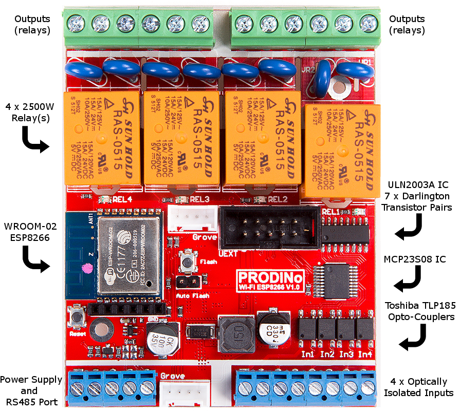
The relays are not driven directly by using the ESP8266 GPIOs but with the help of an MCP23S08 IC (see Figure 2), that is an 8-bit, general purpose, parallel bidirectional I/O expansion for SPI (an I2C version of it, i.e., MCP23008, is also available). The optically isolated inputs use the same MCP23S08 IC (see Figure 2), which means that most of the ESP8266 GPIOs remains practically unused, and most of those I/O pins (including the analog one) are brought out via connectors (which unfortunately are not standard 2.54 male or female headers). To drive the relay coils (requires ~5V@72mA for each), the MCP23S08 is connected to an ULN2003A IC (see Figure 2), which is a 7 port Darlington Transistor Array, allowing an output of up to 50V@300mA per port. This may be a bit of an overkill for this design, but allows for some error margins and also some higher powered relays on future module releases, or...to be replaced by the DIY project author (we love hacking!).

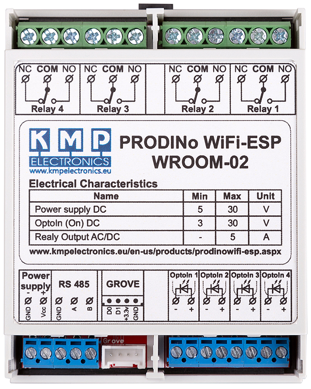
As visible on the product label, shown in Figure 1, the specified output per relay is only 5A, which at the highest voltage (250VAC) means 1250W. We are not sure if this is just a very conservative specification, with respect to the usage of this module, thus allowing for a large safety margin or simply because of some other design considerations that we are not aware of. From our perspective, both the relays (specified for 10A@250V) and the ULN2003A IC that drives the relay coil can easily handle a much higher output (let's say about 2000W, keeping some safety margins).

Programming the PRODINo
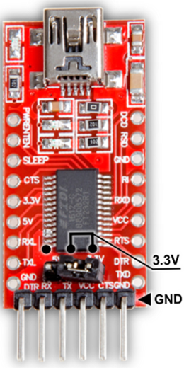
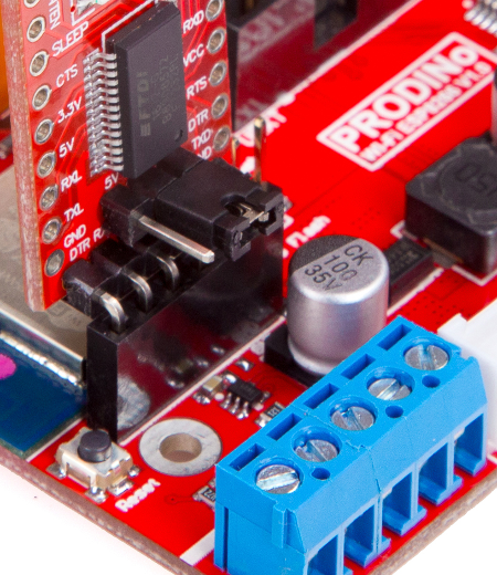
Programming the module requires to use the included FTDI module. However, it is also possible to use a cheap (under 2 EUR) USB-TTL converter module, as long as it supports 3.3V output on its TX (UART transmit) line. Make sure that the FTDI module, that comes on the packet, has the voltage selection jumper set to 3.3V position, as shown in Figure 3. Make sure that you connect the FTDI module in the correct position (see Figure 3), otherwise you may kill the PRODUINo module.
Note: The "Auto-Flash" jumper located just on the right site if the UART connector (see Figure 2), below the "Flash" button, can be set, thus allowing to program the ESP8266 module (the brain of the PRODINo module) without your direct intervention: there is no need to ground the GPIO 0 or to push some sort of "Set to Flash Mode" button. The alternative is to use the "Flash" button, located above the "Auto-Flash" jumper, (see Figure 2). This makes sense when using an USB-TTL module that does not allow to ground the GPIO 0 pin of the ESP8266 module, for all the other cases, just enable the "Auto-Flash" jumper.


Use Arduino IDE to Program a PRODINo Module
It is fairly easy to program the PRODINo module, by simply using the Arduino IDE and Arduino code. Thus, if you ever used the Arduino IDE and wrote some code for one or more of the Arduino boards, you are ready to go with the PRODINo module.
First, you'll need to download the Arduino IDE from the official download page. Make sure that you download the correct version corresponding to your operating system. Also, specially when using UNIX/Linux systems, make sure that your user has the rights to use "COM" ports, that are required by the FTDI module when programming the PRODINo board.
Next, start the Arduino IDE and navigate to File > Preferences menu. In the section "Additional Boards Manager URLs", copy and paste the following URL: https://raw.githubusercontent.com/kmpelectronics/Arduino/master/ProDinoEsp8266/package_prodino-esp8266_index.json, used to indicate the location of the JSON which describes the PRODINo module and the additional Arduino libraries that it requires. Further, use the Tools > Board Manager menu, and from the list of the additional (custom) boards, select the "PRODINo WiFi board by KMP Electronics LTD" one, then click "Install". In a short amount of time, the installation process is completed and we are ready to go with the programming of the PRODINo WiFi-ESP module.
Later, when you'll like to write your custom program to the PRODINo module, use the small arrow icon from the left-top of the Arduino IDE user interface or use the Sketch > upload menu (its keyboard shortcut is CTRL + U). Remember, you'll need to use the Tools menu to select the corresponding board (use: PRODINo WiFi-ESP WROOM-2) and COM port (this can be different from case to case, but usually is something like COM4, COM5, etc).
Controlling the Relays
The first feature we like to test is the control of the four relays. We'll write the most basic Arduino program that allows to switch ON or OFF any of the four relays, by simply using a HTML form. At first, lets write the HTML form, which sends a POST request to the PRODINo module. The full content of the index.html HTML file is shown below:
<!DOCTYPE html>
<html>
  <head>
    <title>PRODINo Relay Controller</title>
  </head>
  <body>
   <form method="POST" action="http://192.168.4.1/relay">
    <label>Select relay:
      <select name="relayId">
        <option value="0">Relay 1</option>
        <option value="1">Relay 2</option>
        <option value="2">Relay 3</option>
        <option value="3">Relay 4</option>
      </select>
    </label>
    <label>Select relay state:
      <select name="relayState">
        <option value="1">On</option>
        <option value="0">Off</option>
      </select>
    </label>
    <input type="submit" value="Save relay state" />
   </form>
  </body>
</html>
Pushing the "Save relay state" form submit button, a standard HTML POST request is made to http://192.168.4.1/relay. The request URL consists of:
- the IP address of our PRODINo module (defaults to 192.168.4.1, but it can be changed if needed or wanted)
- a custom path that handles the requests (we chose to use
/relay)
Two HTML select elements are used for our form. The first one uses the name relayId (this is the parameter name received on the POST request) and allows to select the relay we'll like to control. Allowed values are from 0 (first relay from left to right when watching the relay connectors on the module) to 3 (the most right relay). The second HTML select uses the name, relayState, and allows to specify the state of the selected relay. We'll use 1 for enable (turn ON) and 0 for disable (turn OFF).
Let's now write the Arduino code that intercepts the HTTP post request and turn the corresponding relay ON or OFF based on our selection in the HTML form:
#include <kmpdinowifiesp.h>
#include <kmpcommon.h>
#include <esp8266webserver.h>

const char WIFI_PSK[] = "1a2b3c4d";
const char SSID[] = "Charlie's Home";
const uint8_t PORT = 80;
ESP8266WebServer webServer(PORT);

void setup(void) {
  // initialize the PRODINo board
  KMPDinoWiFiESP.init();
  // setup the WiFi module as AccesPoint (AP Mode).
  WiFi.mode(WIFI_AP);
  // set the SSID and Password for the AP
  WiFi.softAP(SSID, WIFI_PSK);
  // set the HTTP route for the relay control
  webServer.on("/relay", handleRelayRoute);
  // start the web server
  webServer.begin();
}

void loop(void) {
  webServer.handleClient();
}

void handleRelayRoute() {
  int8_t relayId = -1;
  bool relayState = 0;
  // incomming POST request (two expected params: relayId and relayState).
  if (webServer.method() == HTTP_POST && webServer.args() == 2) {
    for (uint8_t i = 0; i < webServer.args(); i++) {
      if (webServer.argName(i) == "relayId") {
        relayId = CharToInt(webServer.arg(i)[0]);
      } else if (webServer.argName(i) == "relayState") {
        relayState = CharToInt(webServer.arg(i)[0]);
      }
    }
    KMPDinoWiFiESP.SetRelayState(relayId, relayState);
    webServer.send(200, TEXT_HTML, "OK");
  } else {
    webServer.send(400, TEXT_HTML, "Bad request");
  }
}
The set of #include directives allows to load the required libraries, which were automatically added when installing the new PRODINo board manager module. Further, for the WiFi name, the WiFi shared password and the server port, the corresponding SSID, WIFI_PSK and PORT constants are defined. Feel free to alter the SSID and WIFI_PSK values, but let the PORT value unchanged (port 80 is the HTTP port).
As part of the Arduino setup method, we initialize the module and set the WiFi in AP (access point) mode. Then, we register the /relay route (as used for the @action attribute of the HTML form element) and the corresponding handler method, i.e., handleRelayRoute. Last, we start the web server by calling its begin method.
The handleRelayRoute method, the handler for the /relay HTTP route, checks if the used HTTP request is of type POST and if there are exactly two parameters provided (recall, we expect the relayId and relayState parameters to be sent). If that is the case, then we extract the relay identifier and the desired relay state, then we change the relay to that state by using the KMPDinoWiFiESP.SetRelayState method and we respond with HTTP code 200, having the meaning "all went fine for the request". If the request type is not of type POST or there are more or less than two parameters, then a HTTP error code 400 is sent, which means "bad request - wrong parameters or request type!"
The Arduino loop method simply waits for requests, by using the ESP8266WebServer.handleClient method.
To test, upload the following code to the PRODINo board (as shown before in this tutorial), then connect to the WiFi network with the name set by the SSID variable. Open the index.html HTML page, and use the form to turn ON or OFF the relays you'll like to test.
Reading the Inputs
The second important feature we like to test is the optically isolated inputs. For this, we'll write a simple Arduino program that is able to read the states of all four optically isolated inputs and return the result. A HTML GET request for the path /opto is used, i.e., http://192.168.4.1/opto. The response is plain text with the format I_x is HIGH | LOW;.
#include <kmpdinowifiesp.h>
#include <kmpcommon.h>
#include <esp8266webserver.h>

const char WIFI_PSK[] = "1a2b3c4d";
const char SSID[] = "Charlie's Home";
const uint8_t PORT = 80;
ESP8266WebServer webServer(PORT);

void setup(void) {
  // initialize the PRODINo board
  KMPDinoWiFiESP.init();
  // setup the WiFi module as AccesPoint (AP Mode).
  WiFi.mode(WIFI_AP);
  // set the SSID and Password for the AP
  WiFi.softAP(SSID, WIFI_PSK);
  // set the HTTP route for the DHT22 sensor readings
  webServer.on("/opto", handleOptoRoute);
  // start the web server
  webServer.begin();
}

void loop(void) {
  webServer.handleClient();
}

void handleOptoRoute() {
  bool optoState;
  String result = "";
  // incomming GET request (get the state of all opto-inputs)
  if (webServer.method() == HTTP_GET) {
    for (uint8_t i = 0; i < 4; i++) {
      optoState = KMPDinoWiFiESP.GetOptoInState(i);
      result.concat("I_");
      result.concat(i);
      result.concat(" is ");
      result.concat(optoState == true ? "HIGH" : "LOW");
      result.concat("; ");
    }
    webServer.send(200, TEXT_HTML, result);
  } else {
    webServer.send(400, TEXT_HTML, "Bad request");
  }
}
Compared with the relays example, we have a few relevant differences. The first one is in the setup method, for which we register the new route, /opto and the new handler, handleOptoRoute. The second change is in the handleOptoRoute method, as part of the request method detection, where now we expect a HTTP GET type instead of POST. The last one is the reading of the optically isolated inputs, made with the help of the KMPDinoWiFiESP.GetOptoInState(inputId) method, which as parameter the input number (0 to 3). A less significant change regards the creation of the GET response body, which consists of chain of "I_x is HIGH | LOW;" strings, one for each of the four inputs (response example: I_0 is LOW; I_1 is HIGH; I_2 is HIGH; I_3 is LOW;).
To test this example, write the Arduino program to your PRODINo board (as shown above in this tutorial), then connect to the WiFi network with the name set by the SSID constant. Open a Web Browser and navigate to http://192.168.4.1/opto. For this case, we don't need an HTML form, since GET is the default request type you get by simply using the URL in the URL bar of a web browser.
Note: Normally, you'll only see only "LOW" states for all the input pins. Also, notice that those inputs are actually in pair of two for each input, since they are practically diodes. You'll need to provide HIGH of LOW states at the corresponding diode end to achieve the expected results. The product cover has labels clearly showing which pin represents which end of the corresponding diode (see also Figure 1).
Homework: Modify the above Arduino program so that the number (0 to 3) of the optically isolated input is provided as part of the HTML GET request, and the response is either "HIGH" or "LOW" depending on the state.
More Examples for PRODINo
It looks that the PRODINo team had a busy time, so an impressive number of usage scenarios and examples are available and ready to use. You'll certainly want to check the Arduino IDE File > Examples > Examples for PRODINo WiFi-ESP menu and chose the one you'll like to test. The example set includes the use of PRODINo as server, access point and client, with the help of the WiFi module and also shows how to provide a HTML interface that allows to control the relays or to show the state of the optically isolated inputs by simply using a web browser, available on any PC or smart device, such as a smartphone, smartwatch or table.
Conclusions
After having quite some fun with the PRODINo WiFi-ESP WROOM-2 v1.0 module and taking a closer look at its hardware components and design, we found it to be user friendly and easy to use for DIY IoT projects, even for beginners. The quality of the board, its electrical design (also check the schematics) and the selection of the electronic components, sets the PRODINo device into the semi-professional category. The price range makes possible its usage for most of the DIY or professional projects / products. Below are the most relevant pros and cons we have found for this module:
Pros
- Low-to-medium price: 40-47 EUR, exclusive shipping costs, but including the FTDI programmer
- DIY ready and user friendly: if you ever played with Arduino IDE and some Arduino boards, you are ready to go with PRODINo
- (almost) Ready to use out of the box: it comes together with the FTDI FTD232R based programmer/debugger module, but notice that you'll need a 5-30V@400mA+ power supply (or an USB breakup cable) and a mini USB cable (for programming only)
- Allows to control four appliances with up to 2500W each: unfortunately, with the current design, it is not possible to directly parallel the outputs for even higher power
- Isolated inputs: Four optically isolated inputs are available, thus the ESP8266 module is safe, even when inputs are misused
- Uses the official WROOM-02 ESP8266 module: ensures a good WiFi experience and allows for lots of hacks and software tweaks, including the use of JavaScript as the programming language, when the appropriate firmware is uploaded;
- (almost) Open source: Its electrical schematics are made public and a module (and corresponding libs) is available for the Arduino IDE board manager, but it is unclear if you are allowed to improve the schematics and release them for public usage;
- Lots of usage examples: After installing the corresponding Arduino IDE module (via the board manager), more than sufficient examples are available (check the
File > Examples > Examples for PRODINomenu in Arduino IDE).
Cons
- (somehow) Limited number of inputs: Only four (optically isolated) inputs are available, keeping in account that the MCP23S08 (8-bit, general purpose, parallel I/O expansion for I2C bus or SPI) is used, and the WROOM-2 module provides itself 9 GPIOs (including SPI and I2C ones);
- Hazard safety, while in general we found this module safe to be used, a better electrical isolation of the (possible mains connected) outputs would have helped to avoid electrical shocks, that can possibly cause injuries or even death (!). This is even more relevant, when the module is used for DIY projects implemented by amateurs. The plastic cover could have been extended over the output connections, thus making the (accidental) touching less probable.
Project Ideas
- Automatic home/garage door locker (and un-locker), based on the location of your smartphone, and home monitoring by reading various available sensors, such as temperature, humidity, light intensity or air quality;
- Control the watering of your home plants or your backyard garden, by reading soil moisture sensors and enabling/disabling water pumps or water pipe connected electro-valves;
- An alarm system that detects intrusion into a home (or perimeter) when we are in holidays, using PIR and capacitive touch sensors, allowing to trigger a high level alarm bugler and sending an e-mail to you whenever something suspicious is detected.
In further tutorials, we'll show how to use JavaScript (Mongoose-IoT based firmware) code to program the PRODINo module. We'll also discuss how to write an Android App to control common used appliances from your house, such as unlocking the door and turning on the light when dark and you just reached the house after a hard work day.
