
Running a Standalone ESP 8266-12 - and Returning from Deep Sleep
This post describes how to actually run a standalone ESP8266-12 when it's been programmed.
Further to my post on programming a standalone ESP8266-12, this post describes how to actually run the ESP when it's been programmed. Specifically, how to wake it up from deep sleep.
A 0.1 uF decoupling capacitor across the ESP8266 Vcc to Gnd inputs very close to the pins (within 1/2 inch). DO NOT SKIP THIS COMPONENT! This cheap yet often overlooked component, when missing, is the root cause of ESP8266 resets."]
Pre-requisites! I'll be using these components:
- @ A standard ESP8266-12 on a breakout-board such as the one shown.
- @ Two 4.7k resistors.
- @ A 3v battery (I use a CR123a) for powering the ESP826612.
The following requirements should be met:
- @ All connections, including those on the ESP 8266-12 on the breakout-board, are solid and conduct power as they should.
- @ The battery holds at least 2.8v of power.
- @ The ESP8266-12 has been programmed with the following sketch:
// Time to sleep (in seconds):
const int sleepTimeS = 5; // 5 seconds

void setup() {

  delay(2000);      // Wait for two seconds
  ESP.deepSleep(sleepTimeS * 1000000);
}

// there's nothing in the loop section - all's done in the setup() section.
void loop() {
}
Given the above is in order, go ahead and connect the components as per the following pictures:
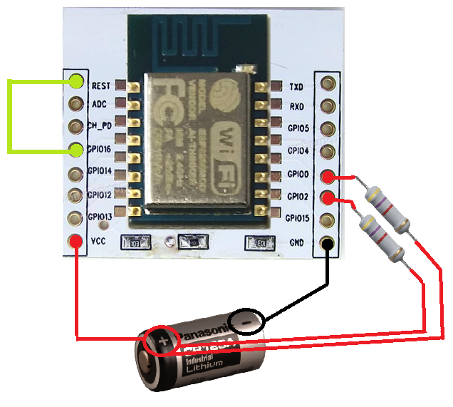
- The RESET and GPIO16 pins should be connected - this enables the ESP 8266-12 to wake up from deep sleep mode.
- The GPIO0 and GPIO2 should be connected to VCC with a 4.7k resistor in the middle. This is to prevent a so-called 'zombie-mode', in which the ESP8266-12 has trouble waking up from deep sleep.
With the ESP connected like so, my ESP8266-12 happily resets/wakes up, does nothing for two seconds, then sleeps again for five seconds before repeating the cycle.
If you look at the tiny blue LED situated just below the ESP and the antenna, you will notice it blinking every ~ 7 seconds, to indicate when the ESP comes back to life.

I measure 15 microampere (uA) when in deep sleep. This will keep the unit running for months on end.