
Connecting to the IBM Watson IoT Platform with Intel® IoT Gateway Software Suites
This guide shows you how to set up and program three key components for designing and developing real-world Internet of Things (IoT) apps
Get access to the new Intel® IoT Developer Kit, a complete hardware and software solution that allows developers to create exciting new solutions with the Intel® Galileo and Intel® Edison boards. Visit the Intel® Developer Zone for IoT.
This guide shows you how to set up and program three key components for designing and developing real-world Internet of Things (IoT) apps:
- Arduino 101*, with the Seeed Studio Grove* Starter Kit Plus – IoT Edition
- Intel® IoT Gateway
- IBM Watson* IoT Platform hosted in the IBM Bluemix* cloud
The Arduino 101* (Figure 1) is a low-power processor board for building a variety of sensor applications. It features a 32-bit Intel® Quark microcontroller, an Intel® Curie module with flash and SRAM memory, a Bluetooth* Low Energy radio, and a 6-axis motion sensor with accelerometers and gyroscopes. It has 14 digital input/output pins (of which 4 can be used as Pulse Width Modulation outputs), 6 analog inputs, SPI and I2C communications interfaces, and a USB interface for serial communications. Its Arduino header allows you to add a variety of Arduino shields for additional I/O and communication capabilities.
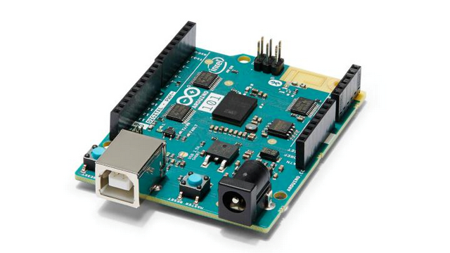
The Arduino 101* can be programmed using the Arduino IDE with standard Arduino programming commands. It can also be controlled remotely using the Firmata protocol and associated Firmata sketch that runs on the Arduino 101*.
Seeed Studio Grove* Starter Kit Plus
The Grove* Starter Kit Plus provides a way to add mix-and-match sensors and actuators to the Arduino 101* to prototype IoT applications (Figure 2). It consists of an Arduino-compatible shield (which plugs into the Arduino 101* base board), with a set of connectors for different types of Grove sensors and actuators. More than 200 Grove sensors and actuators are available, and the Grove Starter Kit Plus contains components such as:
- Temperature sensor
- Buzzer
- Button
- LED indicators
- Sound sensor
- Three-axis digital accelerometer
- Touch sensor
- Light sensor
- LCD character display
- Rotary angle sensor
- Piezo vibration sensor

Intel® IoT Gateways
Intel® IoT Gateways (Figure 3) are edge-processing nodes that combine an Intel processor; a robust operating system; security software; various types of I/O interfaces; and several networking options, including Ethernet, Wi-Fi, and wireless WANs. Gateways tie together groups of individual devices — for example, a set of sensors within a building. They allow hierarchically organized IoT systems and provide critical functions such as local device I/O management (for example, combining data from groups of localized sensors), secure access to upstream systems (for example, cloud platforms), network security and device isolation, remote software updates, and the ability to continue performing local processing in the event of WAN issues.

You can choose from a variety of Intel® IoT Gateways, each with different combinations of capacity, form factor, operating temperature range, and I/O interfaces. Which gateway you use generally depends on the needs of your application and the environment in which it will be deployed (for example, an office environment versus an industrial environment). In this guide an Intel® NUC Kit DE3815TYKHE gateway will be used.
You can use a variety of languages to program Intel® IoT Gateways, including Python*, Node.js*, C/C++, Java*, and graphical environments such as Node-RED.
IBM Watson* IoT Platform
The IBM Watson* IoT Platform running on IBM Bluemix* is a cloud-based platform for connecting devices and gateways in the physical world with scalable processing and storage services running in the cloud (Figure 4). It provides a highly scalable environment for building real-world applications in domains such as asset management, facilities management, manufacturing, supply chain, transportation, energy, and smart cities.
The IBM Watson IoT Platform lets you register and manage devices, connect devices and applications in real time using the industry-standard Message Queuing Telemetry Transport (MQTT) protocol, securely exchange device commands and data, store and access device data, view operations in a powerful web portal, and allow devices to interact with a wide range of other applications and services available in the Bluemix cloud. All these capabilities are critically important when designing IoT applications that will scale to thousands or millions of devices.

The IoT Development Process
Development of IoT applications typically follows these steps:
- Create an initial idea and candidate use cases.
- Test and refine the idea through iterative prototyping.
- Implement and evaluate scalability and product/market fit through pilots and trials.
- Productize the solution and design for manufacturing, and design for scale.
- Bring to market and deploy to production.
- Operate and maintain over time.
The Arduino 101*, Intel® IoT Gateways, and the IBM Watson* IoT Platform provide a rich and scalable set of tools to support each step of such a process, shortening overall time to market while providing the scalability, security, and operational features needed for real-world IoT applications.
How This Guide Is Organized
This guide shows you how to get started with each component and create running applications.
Part 1 explains how to set up the Arduino 101*, Grove* Starter Kit Plus, and the Intel® IoT Gateway. The focus of Part 1 is getting sensors to run in a localized environment and generating data.
Part 2 explains how to connect the components from Part 1 to the IBM Watson* IoT Platform running in Bluemix*, where data can be stored, viewed, and acted upon to create scalable, sensor-driven business applications.
Part 1: Setting Up the Arduino 101*, Seeed Studio Grove* Starter Kit Plus, and Intel® IoT Gateway
The Arduino 101* and Grove* Starter Kit Plus are often used during the iterative prototyping and pilot phases of an IoT project. Their combination of powerful computing, wireless networking, variety of I/O interfaces, Arduino-compatible connectors, and mix-and-match Grove sensors and actuators allow you to turn ideas into running prototypes quickly.
Fun with the Arduino 101 provides a step-by-step guide on how to set up the Arduino 101*, install and use an integrated development environment, connect the Grove Starter Kit Plus, and run example programs that interact with digital and analog sensors.
With the Intel® IoT Gateway, you can build sophisticated IoT applications that require a combination of functionality, security, manageability, and performance. You can connect sensors and actuators directly to a gateway and process and view their data locally. You can also connect groups of sensors (for example, Grove sensors connected to an Arduino 101*) to a gateway for localized processing and to form sensor clusters. Gateways can be securely connected over the Internet to the IBM Watson* IoT Platform so that you can send data to the cloud, where it can be stored, analyzed, and acted upon.
Set Up the Gateway
These instructions apply to an Intel® IoT Gateway model Intel® NUC Kit DE3815TYKHE with an Intel® Atom™ processor. The gateway is preloaded with an operating system image and configured with default system settings. The operating system is the Intel® IoT Gateway Software Suite, a robust Wind River* operating system based on Linux*.
Set up the gateway hardware by making the following connections:
- Connect the power supply and plug it into wall power.
- Connect the gateway to a wired Ethernet LAN network that has connectivity to the Internet.
- You won’t need to connect a VGA monitor or USB keyboard because they’re needed only when you log in to the gateway system console for administrative purposes.
- Connect another computer to the same LAN to allow users to log in to the gateway over the wired network.
Note: The VGA monitor and USB keyboard connections are useful for debugging gateway startup issues or logging in to the gateway system console during development.
For more detailed information about the gateway and setup options, see the Getting Started with Intel® IoT Gateways with Intel® IoT Developer Kit 3.5.
Connect a Sensor to the Gateway
There are several ways to connect sensors to the gateway; the options depend on the specific gateway model you’re using. For the Intel® NUC Kit DE3815TYKHE gateway, you’ll connect an OMEGA* RH-USB Temperature and Humidity sensor to one of the gateway’s USB ports, as shown in Figure 5. The RH-USB sensor measures temperature ranging from 1°F to 120°F, and relative humidity ranging from 2 percent to 98 percent. It works as a serial TTY device through the gateway’s USB port and reports temperature and humidity as an ASCII string.

Power up the gateway by pressing its power button until the light comes on. The gateway will use Dynamic Host Configuration Protocol (DHCP) to obtain an IP address from the wired Ethernet LAN.
Log In to the Intel® IoT Gateway Developer Hub
The Intel® IoT Gateway Software Suite contains a built-in application called the Intel® IoT Gateway Developer Hub, which you use to view gateway status, configure gateway settings, and create sensor applications. The default settings allow you to access the hub over an Ethernet LAN connection at the following address:
- Wired: http://<gateway IP assigned by Ethernet LAN DHCP server>
For example, if the gateway were assigned wired IP address 192.168.22.108, you would access the IoT Gateway Developer Hub at http://192.168.22.108.
Open a web browser, and enter the Intel® IoT Gateway Developer Hub URL. If your gateway is operating in demonstration mode, you may see a Privacy Statement that you need to acknowledge. At the login prompt, use the default user name (gwuser) and default password (gwuser) (Figure 6).

If you see a License Agreement page, review the license agreement, and click Agree if you accept the terms.
Now you’re logged in to the Intel® IoT Gateway Developer Hub, as shown in Figure 7. From here, you can monitor the gateway and its attached sensors, see real-time sensor data, adjust gateway system administration settings, access documentation, and load new software packages.

The status area (1) shows information about the gateway. The sensor widget area (2) shows real-time data from attached sensors. Here, the RH-USB temperature is displayed. In the command area (3), you can navigate among different functions in the gateway by clicking their icons:
- Sensors – display the sensor dashboard.
- Packages – install or update software packages on the gateway.
- Administration – access operating system commands and additional configuration tools.
- Documentation – tutorials, guides and best practices.
Note: The RH-USB temperature sensor will appear as Linux TTY device /dev/ttyRH-USB on the gateway, which is a symbolic link to the physical USB TTY port into which the sensor is plugged—for example, /dev/ttyUSB0. If you plug in other USB devices, the physical TTY port number might shift, so this is the first thing to check if you don’t see the sensor in the Intel® IoT Gateway Developer Hub sensor list.
When you first log into the gateway, there may be updated software packages available. To check for updates, click on the Packages icon and look at the Install Updates button. If it shows updates available, click Install Updates to download and install the updates. It may take some time depending on how many updates are available. After installing the updates, reboot the gateway by clicking Administration and then Restart OS.
Develop a Sensor Application
To program the gateway, you can write code in Python*, Node.js*, and other languages and run it directly on the gateway’s Linux* operating system. However, the gateway also contains a powerful software environment called Node-RED*, which provides a graphical environment for creating, testing, and deploying IoT applications. Node-RED is an open-source, visual tool for wiring together hardware devices, application programming interfaces (APIs), and online services in new and interesting ways. It is written in Node.js, and automatically runs when the gateway starts. For detailed documentation about Node-RED, see the Node-RED Documentation.
To access Node-RED, navigate to the Intel® IoT Gateway Developer Hub’s main portal by clicking the Sensors icon, and then clicking Manage Sensors. Doing so takes you to the Node-RED canvas, where you’ll see a default starter flow for the RH-USB sensor.
A Node-RED application consists of nodes that perform specific operations and wires that connect nodes together to form end-to-end flows. In the web-based user interface (UI), drag and drop the nodes and wires on the canvas using drag-and-drop actions. There are three main types of nodes:
- Input nodes – read data and generate events.
- Output nodes – write data and allow debugging.
- Function nodes – process or transform data and events.
Other types of nodes are used for special purposes, such as email and Twitter integration and disk file I/O. There’s also a large ecosystem of community-developed nodes that you can add to the Node-RED environment to support other types of sensors, send and receive data to cloud services, and perform various processing algorithms. See the Node-RED Library for examples of community-developed nodes.
The gateway also contains built-in support for MQTT, which is an industry-standard machine-to-machine IoT connectivity protocol that follows the Publish–Subscribe architectural pattern. As part of that support, there are built-in sensor data display widgets that you can wire into your gateway Node-RED flow to display data in the Intel® IoT Gateway Developer Hub portal. They display data published to the gateway’s /sensors MQTT topic. To learn how to set up a connection to IBM Bluemix* using MQTT, see Connecting to IBM Bluemix* Internet of Things Using MQTT.
Much has been written about Node-RED, and the Intel® IoT Developer Zone has a step-by-step video to help you get the RH-USB temperature and humidity sensor running on the gateway. Follow the steps described in the video. After completing it, you should see both temperature and humidity displayed on the Intel® IoT Gateway Developer Hub portal (Figure 8).

If you heat or cool the RH-USB temperature probe, you should see the temperature increase or decrease in real time based on the default 1-second sampling rate.
Note: The default RH-USB sampling rate is controlled by the Inject input node labeled Interval in the Node-RED flow. Double-click that node to see its parameters and optionally change the rate. If you make any changes, be sure to click Deploy to deploy your modified flow to the gateway.
Here’s a brief explanation of how the flow works:
- The Interval node generates a trigger message once per second that flows into the RH-USB node.
- The RH-USB node is a subflow that transmits an ASCII command string PA to the RH-USB sensor that’s connected to the /dev/ttyRH-USB serial port on the gateway. The RH-USB sensor returns an ASCII response string over the serial port that’s parsed into separate temperature and humidity values. The separate values flow out of two different output ports of the RH-USB node.
- The temperature value is converted from Fahrenheit to Celsius through a function node. The function node contains a JavaScript* code snippet that performs the conversion calculation.
- The temperature and humidity values flow into chart formatting nodes that set display ranges and attributes for the gateway’s charting widgets.
- The Chart node publishes the formatted sensor data along with the chart display attributes to the gateway’s MQTT /sensors topic, which causes the values to appear on the Intel® IoT Gateway Developer Hub portal.
Notes:
- To change the temperature display from a gauge-based to a time-based line graph, double-click the Temperature node, and change the Type to Line instead of Gauge. Save the change, and deploy the flow; then, you’ll see a line graph for the temperature.
- Function nodes allow you to write arbitrary processing functions in JavaScript. For details about writing your own functions, see the Node-RED Documentation.
Debug Node-RED Flows
An output node named debug is particularly useful for debugging flows (Figure 9).

When you drag the debug node onto the canvas, anything wired into that node will have each data value displayed on the debug tab of the Node-RED canvas. If the debug tab isn’t visible, you can toggle it on or off by turning the Sidebar on or off (Figure 10).

Notes:
- Turn debugging output on or off by clicking the area on the right side of each debug node. Each time you click it, the debug output is toggled on or off.
- Clear existing debug messages by clicking the trash can icon on the debug tab.
- You can use multiple debug nodes in the same flow, each with different connections.
- Use the Comment node to add comments to your flows. Comment nodes aren’t wired to anything, they only contain text. Use them to describe how your flow works.
Role of the Gateway
At this point, the gateway is measuring live sensor data from the RH-USB temperature and humidity probe once per second. The values are processed and formatted to the desired units, and the values are published to the gateway’s MQTT broker, where they’re displayed in real-time on the Intel® IoT Gateway Developer Hub portal.
If you needed to take additional temperature readings—for example, in a different location, you could add another RH-USB probe and expand the Node-RED flow to measure it, as well. The power of using a gateway is that the gateway can connect groups of sensors, process and combine the raw data locally, and then send the data somewhere else for further processing or long-term storage, which is the focus of the next section.
Part 2: Connecting to the IBM Watson* IoT Platform
In this section, you connect the Intel® IoT Gateway to the IBM Watson* IoT Platform and send sensor data to the platform for processing in the cloud. The IBM Watson IoT Platform is a cloud-based environment that lets you design, build, scale, and operate production IoT solutions. It consists of a set of services that you configure and connect in building-block fashion. The Watson IoT Platform services are hosted in the Bluemix* cloud, which means that they can also take advantage of the multitude of other cloud services available in Bluemix.
You can use the IBM Watson IoT Platform in two basic modes: Quickstart and Registered. For details about these modes, see the IBM Watson IoT Platform Documentation.
Connect to the IBM Watson* IoT Platform in Quickstart Mode
Quickstart is an open sandbox that allows you to quickly connect a device and view live sensor data. It’s free, and you don’t have to sign up for anything. You can use either real or simulated devices as data sources: No data is retained over time. Quickstart is useful for getting an initial device connected to the IBM Watson* IoT Platform as you’re ramping up your knowledge of it.
There are several options for connecting the gateway to the IBM Watson IoT Platform, including writing programs in Python* or Node.js*, and creating flows in Node-RED. In this section, you build your Node-RED implementation from the previous section, and use that method to connect the gateway to the IBM Watson IoT Platform.
Start by connecting the gateway to the IBM Watson IoT Platform Quickstart service. To do that, you need a new type of node that knows how to connect to the IBM Watson IoT Platform. An open source Node-RED package named node-red-contrib-ibm-watson-iot does exactly that.
To install the Node-RED components for IBM Watson IoT, add a new package repository to the gateway and install a package from that repository by following these steps:
- Log into the gateway either from another computer on the Ethernet LAN network or by using a keyboard and VGA monitor connected directly to the gateway. For the Ethernet LAN method, if the gateway’s IP address was 192.168.22.100 the login command would be ssh root@192.168.22.100. Use the correct IP address for your gateway.
- For the login username use root and the default password root.
- Run the following command: rpm --import http://iotdk.intel.com/misc/iot_pub.key
- After the command completes you can log out of the gateway command line shell.
The purpose of this command is to install a public key for the Intel software package repository used in the next step.
In the IoT Gateway Developer Hub web interface, perform the following steps:
- Click on the Packages icon and then click the Add Repo button.
- Under Add New Repository, set the Name field to IoT_Cloud and the URL field to http://iotdk.intel.com/repos/iot-cloud/wrlinux7/rcpl13/. Leave the Authentication information blank.
- Click the Add Repository button to add the new repository.
After adding the IoT_Cloud repository it should be listed in the Existing Repositories list (Figure 11). Click X in the upper right corner to close the Manage Repositories dialog box.

Next, install the Node-RED Watson IoT packages by performing these steps:
- Click on the Packages icon and then click the Add Packages button.
- In the search field, type packagegroup-cloud-ibm which should display the package with that name.
- Click Install to install the packagegroup-cloud-ibm package. After the installation completes, click X to exit the package installation dialog box.
- Scroll through the package list to confirm node-red-contrib-ibm-watson-iot shows on the list of installed packages.
Notes:
- The package installation will fail if the repository public key has not been installed.
Next, find the node-red-experience package in the list and click Stop. Then click Start to start it again. The Stop/Start cycle is needed to pick up the newly installed Node-RED package.
Click the Sensors icon and then click Manage Sensors. Along the left side you should now see two new types of nodes called Watson IoT: one in the Input section, and one in the Output section. Use the scrollbars to scroll through the list of available nodes. The new nodes allow you to connect to the IBM Watson IoT Platform. Clicking a node in Node-RED displays it’s documentation on the info tab:
| Input Node |  |
| Output Node |  |
The output node can send data to the IBM Watson IoT Platform, and the input node can receive data from the IBM Watson IoT Platform. You’ll use the output node for your Quickstart connection.
Use your mouse to drag the IBM Watson IoT Platform output node onto the Node-RED canvas. Its name will automatically change to IBM IoT Device. Double-click the node to display its properties. The default values will look like the left panel in Figure 12, with the Quickstart ID being randomly generated. Change the values to look like the right panel (set Name to Send to Watson IoT Quickstart) and then click Ok.

Now, add a wire from the F to C node output to the Send to Watson IoT Quickstart node input. The result should look like Figure 13.

Now, click Deploy to deploy your modified flow to the gateway. Then, double-click the Send to Watson IoT Quickstart node. To the right of the Quickstart Id field, you’ll see a small square button (Figure 14). Click the button to open a new browser window for the Quickstart dashboard, with your randomly generated device ID automatically filled in.

You should see live temperature data in the dashboard (Figure 15), with a time history graph that updates itself once per second. Your gateway has successfully made its first connection to the IBM Watson IoT Platform.
In the Quickstart dashboard in Figure 15, the upper area (1) shows the time history of the received data, and the lower area (2) shows the most recent event data the platform received.

Connect to the IBM Watson* IoT Platform in Registered Mode
Registered mode is the next step up from Quickstart. You register for an account on Bluemix* and set up an instance of the IBM Watson* IoT Platform running on Bluemix. There are free and paid tiers; which you choose generally depends on the data and processing volumes and the number of devices in your application. For this guide you’ll use the free tier, because the number of devices and amount of data will be relatively small.
Registered mode is what you use to create production IoT applications. Create an instance of the IBM Watson IoT Platform running on Bluemix where you can define your device and accumulate data. You’ll also create an instance of IBM Watson IoT Real-Time Insights, which allows you to enrich and monitor data from your devices, visualize what’s happening, and respond to conditions through automated actions.
If you don’t already have a Bluemix account, creating one is the first step. On the IBM Watson IoT Platform Quickstart page, scroll to the bottom and look for the Sign Up button. Alternatively, follow this link.
Bluemix currently has both a "Classic" UI and a "New" UI. This guide uses the New UI, and you can switch to it by clicking Try the new Bluemix. Keep in mind that Bluemix is a dynamic environment, and the UI will evolve over time.
To create a new Bluemix account, click Sign Up, enter the required information, and then click Create Account. Additional information and how-to guides are available on the Bluemix site. The signup process creates an IBM* ID that you use to log in to Bluemix.
Log in to Bluemix by using your newly created account. You should see a welcome page that lists a variety of service categories, including Internet of Things. Click Internet of Things: You should see several available IoT services, including the IBM Watson IoT Platform and IoT Real-Time Insights.
Click the plus sign (+) to add a new service to your Bluemix account, then click Internet of Things Platform. Select the free plan, and then click Create. Bluemix provisions your Internet of Things Platform service; when it’s ready, it appears as a tile in your Bluemix dashboard.
Now, create an instance of the IoT Real-Time Insights service, and select the free plan. When it’s provisioned, your Bluemix dashboard should show both service tiles (Figure 16).

Note: In Bluemix, there’s a main account-level console and individual service dashboards for the various services you add to your account. The process of instantiating a service and adding to your account is called provisioning. After a service is provisioned, it appears as a new tile in your main Bluemix console. The Bluemix console and individual service dashboards will have different URLs. The top-level Bluemix console URL may look something like "https://new-console.ng.bluemix.net" and the Watson IoT Platform console may look like "https://xxxxxxx.internetofthings.ibmcloud.com/dashboard/". You can bookmark the console and dashboards to make them easier to access.
Now, connect the two services so the IoT Real-Time Insights service can get data from the IBM Watson IoT Platform service. The process is described in the IoT Real-Time Insights documentation and is summarized below:
- In the IBM Watson IoT Platform dashboard, generate a new API key. Write down the API key and authentication token. (You can only view the authentication token when it’s first created.)
- In the IoT Real-Time Insights dashboard, add a new data source, and provide the API key information from step 1.
The first time you complete this step, it may take some time during which the browser will be spinning or appear to hang. Give it plenty of time to finish. When setting up the new data source, you enter a name (for this example, name it Intel IoT Gateway), your IBM Watson IoT Platform Organization ID (shown in the Configuration Settings screen of the IBM Watson IoT Platform), and the API key and authentication token created in step 1.
Next, connect the Intel® IoT Gateway to the IBM Watson IoT Platform service as a registered device. Navigate to the Internet of Things Platform service in Bluemix, and launch the dashboard. Along the left side, you see the Boards, Devices, Access, Usage, and Settings icons. Click Devices, and then click Add Device.
Because this is the first time you’re adding a new type of device, you first need to create a new type of device for the Intel® IoT Gateway. If you click the Choose Device Type list, you’ll see that it’s empty because you haven’t created any device types, yet.
Click Create device type, and then choose Create gateway type. In the IBM Watson IoT Platform, there are two categories of connected devices:
- Device – This is an individual device in the IBM Watson IoT Platform, such as a temperature sensor. A device may or may not have an IP address and the ability to communicate over the Internet.
- Gateway – This type of device has additional devices connected to it in a hierarchical or cluster fashion—for example, an Intel® IoT Gateway with two sensors connected to it. Gateways are generally able to communicate over the Internet using IP protocols.
The difference between the device and gateway device types is that for a device, you perform operations directly between the cloud and the device, whereas for a gateway, you perform operations between the cloud, the gateway itself, and the devices connected to the gateway. In essence, the gateway can act as both a pass-through to the devices and as an intermediate device that can perform device data processing before sending data to the cloud.
For details about devices and gateways, see IBM Watson IoT Platform Concepts.
The Create Gateway Type function is a set of step-by-step dialog boxes. Enter the following settings as you step through: - Name: Intel-IoT-Gateway
- Description: The Intel gateway
<Next> - Manufacturer: Checkmarked
<Next> - Manufacturer: Intel
<Next> - Leave the Metadata (optional) field blank
<Next>
<Create>
Now that you’ve created a new Gateway type for the Intel® IoT Gateway, it will appear in the list under Add Device.
Continuing in the Add Device dialog box, choose Intel-IoT-Gateway from the Device Type list, and then click Next. In the Device Info dialog box, create a unique Device ID for the gateway. Use the gateway’s Ethernet MAC address. Enter your gateway’s Ethernet MAC address (including the leading zeros) in the Device ID field, and then click Next. Leave the optional metadata blank, and then click Next. In the Security dialog box, click Next to use an auto-generated authentication token.
On the confirmation page, review all the information. If everything is correct, click Add. If you need to change anything, click Back.
When the gateway device has been added, you get an information screen that contains identifiers and authentication credentials. Be sure to save these credentials somewhere safe, because they can not be recovered later. If you misplace them, you’ll have to delete the device and recreate it. Keep in mind that these credentials are sensitive information, so protect them against unauthorized use.
When you’re finished looking at the new gateway information and printing or saving it, exit the dashboard by clicking the small circled X in the upper right corner.
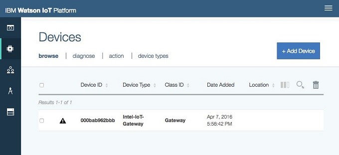
Now, the gateway appears in the Devices list in the IBM Watson IoT Platform dashboard (Figure 17). Note that your Device ID will be different based on the MAC address of your gateway.
Now that the gateway has been defined in the IBM Watson IoT Platform, you can connect to it from the Node-RED flow on the gateway. Going back to the previous Node-RED flow, drag another instance of the Watson IoT output node onto the canvas, and set its properties as shown in Figure 18, being sure to use the correct Device ID for your device. For the Credentials settings, you need the authentication token that you saved when you added the gateway as a new device in the IBM Watson IoT Platform. You also need your Organization ID, which you can find in the IBM Watson IoT Platform Configuration Settings page.

The Watson IoT node expects data in a certain format, so next you add a Function node to format the temperature readings in the correct format. Drag a Function node onto the canvas, double-click it, set the name to Format Temperature, and add the JavaScript* code shown in Figure 19. Click Ok when you’re done adding the code.

Wire the output of F to C to the input of Format Temperature and the output of Format Temperature to the input of Send to Watson IoT Registered. Then, deploy the changed flow. The resulting flow should look like Figure 20.

At this point, live temperature data is being sent from the gateway to both the IBM Watson IoT Platform Quickstart and Registered destinations.
In the IBM Watson IoT Platform dashboard, go to the Devices list and click on your gateway device. You should see a set of Recent Events (changing once per second) and a Temperature reading under Sensor Information. These are the real-time readings that the gateway sends and the IBM Watson IoT Platform receives. Click one of the events under Recent Events: The event data should look something like Figure 21.

This is IBM Watson IoT Platform event JavaScript Object Notation (JSON) that contains a temperature key and corresponding numeric value. It corresponds to the JavaScript code in the Format Temperature node on the gateway:
return { payload:
{ temperature: msg.payload }
};
On the IBM Watson IoT Platform dashboard, navigate to the Boards > All Boards page. The IBM Watson IoT Platform lets you create one or more dashboards (called Boards for short) that display real-time information from your devices. Click on the Usage Overview board, which is a built-in default dashboard. The Intel-IoT-Gateway device should show along with basic data transfer statistics.
Next, add a live display of the temperature value to the Usage Overview board. Navigate to the Settings page, which will display at set of Configuration Settings. Under the General section, turn on Experimental Features, then click Confirm all changes. This allows you to add new information cards to your boards. Cards are configurable display widgets that show different types of information on IBM Watson IoT Platform dashboards. Navigate back to the Usage Overview board and you should now see an Add New Card button at the top right of the page.
IBM Watson IoT Platform Experimental Features are described in the IBM Watson IoT Platform blog post User Interface Experimental Features.
Click Add New Card. In the dialog box that opens, scroll down and click Show more to see all card types. In the Devices section, click Gauge. Choose Intel-IoT-Gateway as the card data source, and then click Next. Click Connect new data set, and then set the following data set fields:
Name: Gateway Temp
Event: event (pick from menu)
Property: temperature (pick from menu)
Type: Float (pick from menu, scroll down to see all options)
Unit: °C (pick from menu)
Precision: 1
Min: 0
Max: 40
Click Next, set size to M (medium), and then click Next. Set Title to Temperature, and then click Submit.
You should now see a new widget on your IBM Watson IoT Platform dashboard that shows a live display of the RH-USB sensor connected to the gateway. If you warm or cool the sensor, the temperature value should increase or decrease in real time on both the IBM Watson IoT Platform dashboard and the gateway’s IBM IoT Gateway Developer Hub display. Figure 22 shows the IBM Watson IoT Platform dashboard with the temperature card added.

Summary and Next Steps
At this point, you have an end-to-end running system that collects real-time sensor measurements, processes and displays the data locally on the Intel® IoT Gateway, and sends the data to the IBM Watson* IoT Platform running on Bluemix. The gateway is programmed using Node-RED, which provides an easy-to-use tool for wiring together processing flows and adding sensors or processing algorithms.
You could add the Arduino 101* and Grover* Starter Kit Plus – IoT Edition to this environment to prototype additional sensors and actuators by connecting the Arduino 101* to the gateway using USB and adding additional types of Node-RED processing nodes for the Grove components.
You’ve also added IoT Real-Time Insights to your Bluemix* environment and connected it to the IBM Watson* IoT Platform service. IoT Real-Time Insights allows you to create if-then logic to monitor sensor data and trigger actions when certain conditions are met—for example, monitoring temperature readings and generating an alert if they exceed a defined range.
Industrial Use Case and Tutorial: Intel and the IBM Watson* IoT Platform builds on and extends the foundation established in this guide. The Industrial Use Case develops a sensing application that continuously measures temperature and humidity, and generates email and text message alerts when parameters fall outside acceptable ranges.
Having the gateway integrated with the IBM Watson IoT Platform on Bluemix opens a range of other possibilities for storing, processing, and visualizing data using a variety of database and application services available on Bluemix. The Intel IoT Gateway coupled with the IBM Watson IoT Platform on Bluemix provides a robust and powerful environment for building and operating scalable IoT applications.