
Biometric Locker- Intel Edison Based IoT Secured Locker With Cloud Based Voice and Face Biometric
4.95/5 (16 votes)
From unboxing to prototype, a complete C# and Node.js Intel Edison product development guide with a real time cloud biometric IoT project
"A Multi Modal Biometric System with Cloud Based Voice Biometric and Face Biometric Written in C# as PC App and a Face and Voice Biometric Node.js IoT App communicating over MqTT And Dropbox's Storage as Service to offer an Intel Edison based Secured Locker with Biometric Security."

- Download BiometricLocker-NodeJsIoT_App.zip - 13 KB
- Download myFirstProject.zip - 8.7 KB
- C# Voice Biometric Face Biometric DropBox MqTT PC IoT App - 28 MB
Index
Part A: Let's Learn
1. Background
2. Getting Started With Intel Edison
2.1 Setting Up Your Development Environment
2.2 Loading OS- Burning Linux Yocto Image to Edison
2.3 Configuring Intel Edison
2.4 Remote Login
2.4.1 Working with Edison through SSH
2.4.2 File Transfer
2.5 Solving WiFi Problem
3. Setting Up Development Environment
3.1 On-Board LED Switching
3.2 Blinking LED, the IoT "Hello World"
3.3 Powering Edison Board
3.4 Getting Started with Intel XDK
4. Embedded and IoT Workflow with Node.js and Grove components
4.1 Mini Project 1: Switch ON and OFF a LED based on a button press
4.2 Mini Project 2: Remote Control with MqTT
4.2.1 MqTT
4.2.2 Working with MqTT in Intel Edison
4.3 Mini Project 3 : Controlling Light Intensity Based on Room Light
4.3.1 Working with LCD in Intel Edison
4.3.2 Working with LDR
4.3.3 PWM- Controlling Light Intensity based on LDR value
4.3.4 Servo Control
5. Setting up Audio and Web Cam in Intel Edison
5.1 Setting Up Web Cam with Intel Edison
5.2 Setting up Audio
Part B: Let's Make
6. System Design
6.1 System Architecture
6.2 Fabrication
6.3 Voice Recognition With Knurld
6.3.1 Understanding Voice Recognition
6.3.2 Knurld API and Services
6.3.3 Knurld Process flow
6.4 Face Verification With Microsoft's Cognitive Service ( Oxford AI)
6.4.1 Understanding face Recognition and Multi Biometric
6.4.2 Micosoft Cognitive Service- Face API
6.5 Dropbox - The bridge between App and Biometric Endpoints
7. Coding-Developing Software Suite for the Locker
7.1 Pc App
7.1.1 Setting And Registration
7.1.2 Voice Registration
7.1.3 Face Registration
7.1.4 A General Approach For Calling Cloud Services in C#
7.2 IoT Device App
8. Conclusion
Part A: Let's Learn
1. Background
Beside the usual "billions of connected devices and a trillion dollar economy by 2020" , the other most common statement that often gets associated with IoT is "security is a challenge". How do we create more secured framework for establishing more secured communication between a device and a cloud and among the edge devices is one of the areas of research and development in IoT. When I started planning about an IoT project for this tutorial, I wanted to work with security aspect of IoT. My initial plan was to work on various levels of encryption and write a tutorial around that. But then I realized that a tutorial without a solid use case will not of much use to the readers. I also wanted to review the security context being offered by IoT ecosystem in the context of an end product. So, I started thinking about a product that can showcase the security aspect. A cashbox is generally used by small businesses to keep daily transaction money. Many of us have lockers at home too. We keep essentials and valuables in lockers. Traditionally lockers are being protected with keys which are easy to forge. Some of the cutting edge lockers also offers fingerprint verification based system. A biometric based user authentication is considered to be more sophisticated security extension for such locks. So, I thought biometric security would be a great system to build if I have to create a highly secured system.
Needless to say, these systems works in an offline context and are pretty much independent system. So I thought "wouldn't it be nice to have a secured locker that can run on IoT ecosystem?"
Now, this thought is not merely because I wanted to develop a secured system around IoT and cloud, but there is certain advantage to it over the traditional system. The first is the scalability of the solution. For instance, let us consider a bank locker system. Different account holders have individual lockers. Let us assume that the bank implements an offline solution, as the customer base grows, the system would face severe scalability issues. Let us now assume that bank wants to create some more branches. In each of the branches the users that holds the lockers would have to be manually registered. If a customer changes the location, he usually needs to release current locker and go for a new one in new location. This becomes a tedious process for the banks. So, scalability and mobility becomes the core issues with offline biometric solution. The other important issue is that of the security of the biometric system itself. Ensuring that the biometric trait database is secured in the local server is also challenging. There is an entire suit of services and solutions for ensuring data security in the local storage.
Now, think what if we can take the solution to the core instead of keeping it at the edge? The core or the cloud as it is now being commonly referred, is an extremely scalable infrastructure with high level of reliability, security and computation power out of the box. Now imagine, if the biometric solution of the bank locker that we discussed is implemented at the cloud, a bank wouldn't have to worry about local security of the records, maintaining the system, scalability or mobility of the customers. They can focus on their business where as the security and scalability would be taken care by the cloud. This indeed was the motivation of this project called Biometric Locker.
The cloud also offers other advantages. For instance, a bank can easily offer mobile based verification system. So the biometric trait of the user collected for the locker can be easily extended to other core banking services. For example user can use his biometric trait to access his internet banking. Banks can extend the service to ATMs. They can even be extended to mobile banking. Mobiles being the most popular platform for personal and even some of the enterprise applications now, makes it even more important for the services to be in the cloud such that they can be extended across different devices and service areas.
So, a cloud based biometric locker was a good product to build from both an IoT ecosystem point of view, as well as a scalable enterprise security system.
But there is one other aspect that needed some thought. Which biometric traits? Iris, fingerprint, face, voice, palm prints are some of the popular choices of the biometric traits. But which can be cost effective and a scalable trait? Face immediately comes to our mind. Why? because it needs no extra hardware. A mobile has a camera, tablet has a camera, laptops have cameras. But, biometric systems are often vulnerable. For example a face biometric system can be easily gamed by presenting a high definition photograph of the user in front of camera. Liveliness detection system was built to counter this threat where a user is asked dynamically to make some facial gesture like smile or blink eye. If user could follow that, he would be considered as alive and his face will be verified. However, unfortunately due to requirement of subsequent frames for such a detection, many commercial face biometric providers have failed to offer this solution out of the box. Which is the other way to verify the user? Voice, of course. If user is asked to speak out certain phrases in random orders, then he would be considered as alive. It further enhances the security of the system. But the best part is that, like face, even this system needs no special hardware as tablets, mobiles and laptops all have MIC which can be used to record user's voice.
So, a cloud based biometric system with combined face and voice biometric would be an ideal mobile, scalable and reliable security ( authentication in more finer term) system would be the most obvious choice for a security system.
An efficient IoT ecosystem can be built only if sufficient thought is put behind connecting not only "things" but also the clients. So we propose a novel "Cloud Based Face and Voice Biometric powered Secured locker". However, our focus for this tutorial will be around implementing these techniques in edge IoT device( because at the end locker is a thing and the thing has to be secured).
The last ,most important question was "which device?" Raspberry Pi? Beagle Bone? Arduino Yun? After not so much thought as much I spent on the concept, I decided to go with Intel Edison. Why?
Because, trust me, nothing gets your IoT prototyping easier in comparison to Intel Edison and you would learn and admit that by the course of this tutorial. On a side note( you are welcomed not to note it at all) I am an Intel Software innovator and I have weakness around Intel technologies. Also, Intel have been kind enough to offer me the entire hardware kit for free( yay!!! the secret revealed). But, even if you don't get it for free and need to spend some amount on it, I advise you do so. Because Intel Edison and Grove kit combo can really bring out IoT skills to even a 10 year old kid.
Organization of the article
When I worked out the problem space that I want to work with, next obvious question for me was what I want to cover through this tutorial.
A simpler choice would have been to drop certain external links for some getting started guides and keep the focus area of this article around the core concept. But then I thought, if I am creating a product from the scratch, why not build a tutorial of the complete stack? From conceptualization to design and prototyping? So, instead of limiting this article as a code or hardware explanation limited to our Biometric Locker, I decided to guide a completely novice and never exposed to IoT ecosystem guy ( or girl!!! no gender bias intended! ) to encourage, help, guide and mentor to develop a commercial grade IoT product.
If you are already a punter in IoT, or an Arduino DIY guy and you already know things about "things", you can straight away jump to the section that introduces the security. If you are a security professional and you want to know how your skills can be used in IoT, you can use the tutorial to skip through security topics and focus on the IoT aspect. Whether you are a professional, or a hobbyist, or just a curious reader, you would found something interesting to learn from this article. If you do, just put a comment. Are you ready? Awesome, so let's get started. But, before that, a general warning:- this is going to be one huge article, so you are advised to bookmark this, make sure your coffee or beer stock(whatever you prefer) lasts till the end of the reading.
If you are already an active developer or a DIY or a hacker, skip the next paragraph, the absolute beginners are advised to read the footnote of this section.
Some quick getting started links for the beginners:
As IoT consists of framework, protocols, connectivity, cloud, hubs, buses, devices, standards and many more, you are advised to follow some basic tutorial and articles in IoT. If you have never worked with hardware before, I advise you to get yourself an Arduino UNO board first, get your hand dirty with some basic hardware hack and programming and then get started with this tutorial. Here are couple of quick links for you that might help you to accelerate your IoT learning.
1. Introduction to Internet of Things
2. Complete Beginner's Guide For Arduino Hardware Platform For DIY
Chapter 2: Getting Started With Intel Edison
In this chapter, we will learn about setting up our device, flashing operating system image, connecting the device to internet, allocating ip address, and some work around about Edison WiFi problems. This chapter is specifically for those of you who has just got an Edison board. Those of you who already have a board set up can straight way go to chapter 3.
2.1 Setting Up your development environment
This project is a multi-programming language-, multi-architecture, multi-hardware, multi-protocol stack and therefore need many tools, technologies. So, you are advised to grab all the necessary tools and install them to kick start making this project.
Hardware:
- Intel Edison with Arduino Expandable Board.( Amazon Link)
- Intel Edison Power Adapter ( I shall reveal why it is important in due course of time)
- A UVC Compatible USB web camera ( camera with microphone would be the most ideal choice)[ list of all the UVC compatible camera vendors]
- A Bluetooth microphone ( we are not going to use it in this tutorial. So if you already have a camera and Bluetooth microphone, then that is fine. I am just going to share some links for configuring Bluetooth microphone. However, be advised that separate microphone and camera will have performance issues)
- Grove Kit for Intel Edison( Amazon Link)
- A Grove compatible Servo motor( if your Grove kit doesn't come with one).
- USB Driver for Edison
- 7-zip for decompressing Yocto image
- PuTTY to connect to the board through SSH or Serial interface
- WinScp or FileZilla for easily transferring the files to and from Edison board
- Visual Studio 2015 Community edition. (I use VS2012). for developing our C# Client.
- Intel Edison Yocto build image
- Intel XDK IoT edition
- Bonjour from Apple for automatic discovery of IoT devices
- MyMqTT App in your mobile
You would need to setup many other tools which are not really required at this stage. You are starting with Intel Edison and IoT and therefore you need at least these tools. But more than anything, you need a good internet connection( after all it's INTERNET of things).
2.2 Loading OS- Burning Linux Yocto Image to Edison
There are tons of tutorials( here is one official tutorial by Intel->Flashing Firmware into Edison) about getting started guide with Edison. So I could easily avoid this section. However, to maintain the continuity of this article and to cover a complete end to end process of IoT product development with Edison, I would cover the firmware flashing part here.
If you have just got your brand new Edison board, you can follow the steps in figure 2.1 to unbox and prepare your Edison board.

Figure 2.1 Unboxing Intel Edison Board
Before you start with flashing, you have to power up the board. Please see figure 2.2 to know what each port and switches do in Edison board.
 Figure 2.2 Understanding the switches and ports of Intel Edison
As you can see in the above figure, the first micro USB port ( the one after power selection switch) is used to flash firmware into Edison as well as is used for powering up the board through USB. So for flashing, it is sufficient that you connect a single USB cable with this port and proceed with flashing process. You can see the connection in figure 2.3
 Figure 2.3: Connection Setup for Flashing
We will be using a utility called dfu-util( device firmware upgrade utility). Please go to the official dfu-util(http://dfu-util.sourceforge.net/) Source forge page and then from release folder download the windows exe (http://dfu-util.sourceforge.net/releases/dfu-util-0.8-binaries/win32-mingw32).
This tool in turn depends upon another tool called libusb which can be downloaded from the same Source forge release directory of df-utils (http://dfu-util.sourceforge.net/releases/dfu-util-0.8-binaries/win32-mingw32/libusb-1.0.dll).
Once you have downloaded the Yocto zip file( it would be named as iot-devkit-prof-dev-image-Edison-20160xxx.zip), right click ->7-zip->Extract Files, select a folder for extraction.
An obvious question here is why we need a separate zip/unzip pack and what's wrong with using WinRar or even windows out of the box unzip utility? Well, the reason is that the Linux distribution has some really deep nested files where the absolute path is extremely huge. Windows Unzip utility can not handle such large file path. Therefore we need 7-Zip. If you do not use 7-Zip, chances are that your installation will not completed successfully. Once the folder is unzipped, copy df-utils.exe and lib-usb.dll into this unzipped folder.
Your folder should look similar to following figure 2.4.

Figure 2.4 Directory view of unzipped Yocto with df-util and libusb
All you need to do is plug both the cables, make sure that Edison board power switch is towards USB ( don't worry, we shall discuss about powering up the board in another section). You can see following image to be sure of the connectivity.
Find and double click FlashAll.bat it should prompt you to reboot as bellow.

Figure 2.5 Initiating Flashing Process with flashall.bat
You can reboot Edison by pressing reset button ( see figure 2.2)on the board.
If things goes as par plan the installation will be completed and flashall command window will get closed.
It's time to connect the serial port with second micro USB, if you have not connected that while flashing. Connect your serial port to last micro usb port (figure 2.2).
Now when you right click on My-PC ( or My-Computer in Windows 7) and select properties->device manager under LPT ports you will see a new entry as shown in figure 2.6.

Figure 2.6: Detecting USB Serial Port for Edison
So, now your Edison board is connected to PC using Serial port. It's time to test if the board boots or not.
Open Putty. Select Serial radio button instead of default SSH and make sure that you have set the baud rate to 115200. The Edison board doesn't work with 9600 or 19200 baud rate which you may be habituated with if you have used Arduino earlier. Enter your comport and hit 'open'.

Figure 2.7 : Connecting to Edison board via Serial USB using PuTTY
You will see your Edison board booting as shown in figure 2.8 below.

After booting, Edison prompts you for user name, which is root. Password is not yet configured. So once you give root, you will see root@edison# prompt as shown below in figure 2.9. From here onwards we will refer this prompt as Edison shell.

Figure 2.9 User Login in Edison
Voila. You have just completed the first step- i.e. setting up your board. Cheer up yourself, you have done a great job. Take a break. When you comeback, we will start with the next important step, i.e.. configuring the board.
2.3 Configuring Intel Edison
There are few things to do before we can actually start coding with Edison. The first thing to be noted is that, Edison is an IoT device. IoT devices are needed to exchange messages through many secured and in-secured gateways locally as well as globally. So setting up a unique name and password for the board is a very important step towards getting things working properly. It is extremely simple. You can configure and setup the board with a single command in Edison shell.
configure_Edison --setup
First, it will prompt you for a password as shown below in figure 2.10

Figure 2.10 Password setup in Edison
Next, it will prompt you to enter a unique name for the device. If you are connecting many Edison devices in your network, which is basic requirement in many home automation as well as industrial application, then DNS needs a way to resolve the ip address of the devices. It is advised that you give a unique name to your device in order to avoid a DNS-IP conflict or DNS resolve error following figure shows device name setup.

Figure 2.11 Edison Device name setup
Once device name is setup, it will prompt you for password. Enter a password. If you are in production environment, create a strong password is recommended.
it will now ask whether you want to set up WiFi or not. Just type y and enter.
It will show you list of WiFi Networks where you have to select the network you want to get connected to, when it asks for confirmation, enter y and then enter your WiFi password.

Figure 2.12 Wifi setup in Edison
If things go as smooth as they often do, then you will see a dynamic IP address being assigned to your device. This is of course a local IP address corresponding to the your local network.
Now test your internet connectivity by pinging google.com. If you see packets exchange is successful in ping, then your internet is connected and you are almost ready to rock with your board.
(use ctrl+c) to stop ping.
 Figure 2.13 : Ping test for checking internet connectivity
This is the optimal setup you need to get started with IoT with Intel Edison. During the course of this tutorial we need to set up several other things like a web camera, audio, Bluetooth and so on. We shall skip those setup at this stage and cover them appropriately just before we start using them.
By the way, if you have reached till this point, you have done a great job so far.
Note(important for beginners):
When you are login for the second time through serial port in PuTTY, after hitting open button, you will see a blank console. Don't worry, just press enter and you will be to login shell.
2.4 Remote Login
Having setup our device, the first thing we need to do is to test if we are able to login to our Edison board remotely or not. In most of the cases, we will be deploying our IoT app with the device as an independent entity. That must not require any laptop connectivity for coding and debugging. We will explore two different techniques here: first one is SSH which is one of the most important tools ever developed (particularly for IoT), the second one is remote file transfer via WinScp. File transfers are important to backup your code, extracting sensors log from device, storing configuration files.
2.4.1 Working with Edison through SSH
Secured Shell or SSH as it is commonly referred gives you the power to log into your device even if your device is not connected to your laptop. SSH also gives you the power to work with Edison from any operating system. Once IP address is configured in Edison and it is in your local network, you can SSH to device from Unix shell or from mac with following command. It will prompt you for password. Enter the Edison password. You will be logged in Edison and you can work with the device.
ssh root@<Edison_ip_address>
As, my focus is on windows environment, I will be using PuTTY for remote login( you can also use PuTTY with Linux or Mac).

If you are using PuTTY, enter Edison_ip_address in IP address text box after selecting default SSH radio button as shown in above figure 2.14 and hit open.
As SSH establishes a secured communication, putty exchanges a certificate with your board. So, when you are using PuTTY for SSH to a particular device for the first time, it will show you a security warning with the exchanged certificate. Just accespt and you are done. It will prompt you with root.

Figure 2.15 : SSH Security Warning
Note that SSH doesn't require a serial communication. So, you can very well unplug the last micro usb cable ( serial port cable as in figure 2.2 and then test the SSH command.
The great thing about Edison is that it supports Multi-Session. So you can login to same board from different PC through SSH at the same time. You can also use two putty windows: one for SSH and other with Serial in the same PC.
Following figure 2.16 shows how I logged into my Edison device in two different sessions, one using Serial port and the other using SSH

Figure 2.16: Multi Session with Intel Edison
So, if you are a team lead or a senior, and one of your team mate is struck in a code, you can always login to his machine through SSH and access a copy of his current code :). More than one developers may also work in different projects simultaneously with Edison (!not tested)
2.4.2 File Transfer
While working with IoT devices, many a times you need to exchange files like: downloading log files, uploading configuration files and so on. It is therefore recommended to setup a file transfer tool at this stage itself. Though this is not an essential step for this current project, you may need while working with Audio and video.
There are many file transfer tools. FileZilla is a very popular tool. If you are using FileZilla, you can login to your board via SFTP as shown in figure 2.17.

Figure 2.17 : Setting up SFTP through FileZilla
Don't forget to change the default port 80 to 22. Once you login to device, you will see your Edison root folder on right and your working directory on left as shown in figure 2.18.

Figure 2.18 FileZilla Structure
You can transfer file to and from Edison by dragging the file from and to your pc's local directory. WinScp supports only SFTP and therefore is little simpler for the beginners. Following figure 2.19 shows a WinScp screenshot.

I personally prefer to use WinScp, but you can use any of the tools you are comfortable with. You can transfer some files to Edison, ls in shell and see if the transfer is successful or not. This should have been the end of chapter 2, but I want to cover another important topic which is included as a hack to solve WiFi problem. You need not to follow this subtopic here, but taking a glance at this topic will make you aware of the type of problem you may face with Edison's WiFi and how to workaround with that problem
2.5 Solving WiFi Problem
Many a times, if your WiFi is not reliable, or of weak signal strength, Edison doesn't get connected properly. So even though an IP address is associated with the device, the device will refuse to get connected via SSH. In case you are getting such connection problems, login through serial mode, and test ping google.com. If you see that the device is not pinging google ( it will shoot a command response "bad address google not found"), you need to manually re-configure Edison again( if your WiFi is working properly). As a first step you can generate reboot command from serial putty and after loggin in test ping again. If the device still doesn't get connected, in shell generate
configure_Edison --WiFi
Follow the WiFi setup steps once more. You should now be able to access the device once more through Edison.
One of the problems with reconfiguring WiFi is that Edison stores the WiFi configuration in a file /etc/wpa_supplicant/wpa_supplicant.conf
Each time you reconfigure, your settings are added to this file( even if you are entering the same network and password). If the file grows too big, or if internal write operation gets corrupted, then you will see an error after configure_Edison --WiFi which can be either no ssids shown, or failed to connect to global_iframe as shown in figure 2.20

Figure 2.20 Common WiFi problems in Edison
In case you get any of the above errors, do not worry. Here is a workaround of the problem.
- Remove the configuration file.
-
rm /etc/wpa_supplicant/wpa_supplicant.conf
- create a new configuration file with vi command
-
vi /etc/wpa_supplicant/wpa_supplicant.conf
- copy and and right click on vi editor to paste the contents the following configuration template
-
ctrl_interface=/var/run/wpa_supplicant ctrl_interface_group=0 update_config=1 fast_reauth=1 device_name=Edison manufacturer=Intel model_name=Edison network={ ssid="YOURSSID" scan_ssid=1 key_mgmt=NONE auth_alg=OPEN wep_key0=f0039faded348299992344be23 } - ESC :wq to save and come out of vi editor.
- reboot
Now again got Wifi setup stage and you should be fine :). Note that after reconfiguration, your ip address may get changed. Please check and note down the ip address.
Note: If you are unable to paste on vi editor through right click, click on the top of shell to bring out change settings and make sure you have property being set as par following figure:
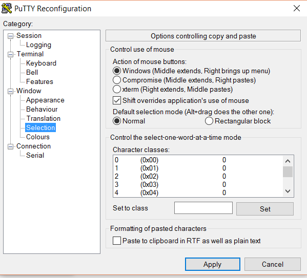
Figure 2.21 Desired PuTTY property for ability to copy paste
Well, that marks the completion of chapter 2. Here is a summery of what we learnt in chapter 2
Chapter Summery: What we learnt
- Unboxing Edison
- Flashing Yocto image into Edison
- Setup serial communication from PC to Edison
- logged in to Edison board via PuTTY and SSH
- File transfer to Edison using WinSCP or FileZilla
- And finally a work around to solve common WiFi problems in Edison.
3. Setting up Development Environment
In this chapter, we will learn about setting up our development environment, executing some basic programs in Node.js, understanding power and hardware components.
Edison supports many coding languages. Python, Arduino C and Node.js are some of these platforms. I love Node.js because of the simplicity of the language, plenty of libraries being available and support of Edison out of the box. So if you have setup the board using the steps covered in chapter 2, you do not need any other configuration. You can start coding :)
In this chapter, our focus will be understand writing simple codes in Node.js. It is better that you follow some great online tutorials on Node.js.
I particularly advise beginners to follow this Tutorial Point Node.js Tutorial which has inline execution option. So you can try the code as you learn.
However, through the course of this tutorial, we will cover important aspects of Node.js relevant to IoT context.
We will use Intel XDK IoT edition for writing, debugging, running and deploying the code. But, before we switch to Intel XDK, we will execute our first simple node.js program in vi editor to check every thing is setup perfectly.
Once we are done testing our first program ( which will be switching on-board LED of the board), we will discuss about powering up our Edison in different ways. Then we shall learn how to use different hardware components with Edison. Here is the agenda of this chapter:
- Simple On-Board LED glowing through Node.js code from vi editor
- Learning about powering option for Intel Edison
- Getting Started with Intel XDK
- Grove Sheild Connection
- preparing Intel XDK IoT edition for coding and debugging
Ready? Let's start "making"
3.1 On-Board LED Switching
Edison supports Node.js out of the box. So, you can straight away start codeing through vi editor. In your PuTTY Edison Shell type first.vi. Hit insert or 'i' key and type the following listing.
var mraa=require('mraa')
var ledPin=new mraa.Gpio(13);
ledPin.dir(mraa.DIR_OUT);
ledPin.write(1);
Press escape, then :wq and enter to save and exit.
To execute the script, type
node first.js
Look at your board. On board LED, which is hooked to pin 13 will now be on as shown in figure 3.1 below.

Figure 3.1: Onboard LED Switching
Awesome! You are on your way. Now, turn off this LED by changing the program!!!
Ok, getting back to what this program does!
mraa is a node.js wrapper of Libmraa which is a library written in C++ to access the hardware ports of Embedded and IoT devices running Unix.
Intel Edison Arduino expendable board has digital and analog pins just like Arduino. You are advised to read the Arduino article link I shared at the beginning of this tutorial if you are not aware of the actuators and sensors.
The on-board LED just like Arduino is hooked to pin 13. The pins are dual input out(DIP) type. So first we declare an object of mraa library called mraa. Now we access the pin 13 by declaring a variable called ledPin as a new instance of type mraa.Gpio() . As the pins can be used as input or output( but remember only of one type at any moment), we need tospecify the pin type through mraa.DIR_OUT or mraa.DIR_IN. As, we want to control the LED, LED needs to be an output device. Hence we select the direction as DIR_OUT. finally using write function to write 1 or 0 which results in turning on and off of the bulb respectively.
As, javascript is a scripting language, we do not need to define an entry point for the program. The program is executed from the first instruction.
However, you can observe one thing, the moment you execute the program, the LED will be on and your shell prompt will return. Which means that the program is finished executing. By definition, a microcontroller or embedded microprocessor is expected to run in an infinite loop, repeating the same sets of instructions over and over again differed by a time delay( recall the void loop() function of Arduino). So, in order to have our program do the same thing, we are going to create our own loop() function for node.js and extend our basic LED switching program into LED blinking which is considered as "Hello World" for embedded systems and IoT.
3.2 Blinking LED, the IoT "Hello World"
In node.js we can call a function asynchronously after predefined time period using setTimeout() function. Following is the general structure of a loop() that calls itself in every 1000 ms.
function loop()

{

 //your code goes here

setTimeout(loop,1000); // recurssion in every 1000ms

}
You can write your main login in this function and from the script, you can simply call this function. Following in the blink.js code developed by tweaking first.js and above loop template.
//listing blink.js

var mraa=require('mraa')
var ledPin=new mraa.Gpio(13);
ledPin.dir(mraa.DIR_OUT);
var ledState=0;
loop();
function loop()
{
        if(ledState==1)
        {

                ledState=0;
        }
        else
        {

                ledState=1;
        }
 ledPin.write(ledState);
setTimeout(loop,1000);
//ledPin.write(1);
}
We simply introduce a variable called ledState and invert it's value every time the loop is called. One obvious question that may come to mind is why not using a boolean variable instead? Because, write() expects it's parameter to be of integer type. So we use a number. Execute this code and you will see the onboard LED blinking in every 1 sec.
Can you alter this program to keep the LED on for 5 sec and off for 1 sec? Try out by yourself.
If your LED is blinking, you are now ready to start using hardware. We will start with Grove shield. But, before we use Grove sheild, I would introduce another sub-topic called powering up the board. As you read on, you would come to know the importance of understanding power and different power options that can be used with Edison and their use cases.
3.3 Powering Edison Board
One of the obvious question that may come to your mind would be "why the topic is introduced here? It should have been right at the beginning.Because, powering is after all one of the basic things".
Well, once we have a new toy, we want to get started with it first. We want to open, and have it's basic functionality. Then we start exploring the features. Blinking LED is one of the most important confidence boosters when you start working with an IoT component. So, I covered the essentials to help you reach upto this stage and understanding the hardware and program structure a little. Once you are at this stage, you have a ready working board to tinker with.
Table presented in figure 3.2 shows the different powering options, how to connect to Edison, their rating and use cases.

Figure 3.2 Intel edison powering up options
Generally I use the power bankfor my all non-camera based Intel Edison project because of mobility, good current rating and ease of use. I advise you not to power up Edison using USB as it has very poor current output. So, if you are using laptop to power up Edison, be prepared to frequent reboot and crash when many components are in used. Also, web cams do not work with USB powere board.
For robotic projects with 12v motor and relays and camera 12v battery is advise. Important things to note here is that many of these batteries have high current ratings like 5A or 7A. Please be sure to check the rating and go for batteries which offer 1.2A to 1.5A max.
The above table will be in your Edison reference list and would help you chose a power sourrce based on your requirement.
There is just one more setup before you can start working with serious IoT stuff with Edison
3.4 Using Grove Kit With Edison
"Time is money".
When you are prototyping, you want your model to be ready as quick as possible for a proof of concept. Image what if Copy-Paste was never invented? How many of us would still be an efficient coder? Code reusibility makes the software prototyping extremely fast and efficient. But the same isn't always true for hardware. You need to hook up connections, test voltage, power, have various connections and find out that something isn't working. You reopen the connection. Bread boards are one of the choices for temporary connection, but let's face it, you can't ever build a prototype on bread board and take it before the investors. They don't look neat, plus there is always a thick chance of connections coming out. Even though Arduino made the connections relatively simple by offering the most basic needs for a hardware prototyping out of the box, you still had to hook up the external components.
Grove kit by seed studio is one of the major leap towards making hardware prototyping simple. It allwows you to make good prototype at a fast pace, without worrying much about the connections.
So, let's begin with our Grove kit.
Let's open our Grove kit pack. You can see several components in slots. I prefer to mark them with marker so that I can place back the components after I am done with certain experiment. Here is how Grove kit looks.

Figure 3.3: Grove Kit Components: Inside the Grove kit box
I advise you to mark the solts so that you can always keep a track of your components. When you open remove the LCD, beneath it, you will find the base shield as shown in figure 3.4
Now take out the Grove Base Shield as shown in 3.4 (a) and mount it on top of Edison Board as shown in figure 3.4(b). Ensure that the base shield has sit properly on the slot.

Figure 3.4 : Connecting Grove Base Shield with Edison
3.5 Connecting Hardware Components to Base Shield
Figure 3.5 Explains how to hook up Grove components with base Shield. The logic is pretty simple. Connect sensors with Analog ports, digital switches or output like Relay and LEDs with Digital port. If you want to use PWN for Speed control or Intensity control, use D5 or D6 which are PWM ports. LCD or Accelerometer must be connected to I2C port.

Figure 3.5 : How to connect components with Grove Shield
But, where are the connecting wires? pull up your white slotted box holding the components and you will see the connecting cables. Just take out the cable and connect one end to the component and the other end to the base shield port as per the table in figure 3.5 .
For those of you who are still unable to find the connecting cables and confused, refer to figure 3.6

Figure 3.6 Connecting Grove Component with Base Shield
The cables will get connected only in one way, so you need not to worry about a wrong connection. But if you really want to know the trick to "connect without confusion"?
Black wire goes to 'GND' marked side of the port. ( see above image)
In above figure, I have connected buzzer with D4. If you also connect the same, you can easily test it by changing pin number from 13 to 4 in blinking.js.
If you go through my Arduino tutorial that I had mentioned at the beginning of this tutorial and compare the effort I had to make in rigging up each of the circuits with the circuit you built, you would realize the revolution Seed's Grove kit brings with it!
Okey, so now you have flashed your Yocto, configured Wifi, tested LED blinking, connected Grove kit and tested it. It is now time to get started with serious coding and prototyping with the board.
3.6 Getting Started with Intel XDK
You have already developed a simple program in vi editor. So, an obvious question may be "why we need another software?". Well, vi editor is great to get started but is not ideal for large and real time projects as it doesn't have code searching, module maintanance, intellisense and other minimum requirement for clean coding.
Another question that might come to your mind is that why we did not set it up early? Because Intel Edison needs WiFi to get connected with your device. Once WiFi is setup, you definately want to test your board is working or not. Right?
Once you have followed all above steps, you are already a confident IoT starter. So let's complete the journey from beginner to intermediate.
Before you start Intel XDK, ensure that you have installed Bonjour as listed in software requirement section. This is used by XDK to discover your Edison.
The XDK would ask you to register an account with Intel when you run it for the first time. Once you have registered, sign in with your account.
In the bottom click on the combo box with text '-select a device-'. if your device is up and running in the network, XDK will automatically detect the device and show you in the list as shown in figure 3.7.

Figure 3.7 Device selection in XDK
If you are connecting te device for the first time, then it will prompt you for the password for default user root. Once you enter the password, you would be alerted that "your device is connected".
Click on the top project tab and then select "create new project" from the bottom as shown in figure 3.8

Figure 3.8 Creating a new project in XDK
Now select, Internet of things Node.js project. XDK comes preloaded with tons of ready projects for you to qucikly learn IoT coding. But, I am not too big fan of these templates. So, I would rather prefer a fresh and blank project for you start with bare minimum and then keep adding your devices and codes on top of it.
So, select blank template as shown in figure 3.9
![]()
Figure 3.9: Project type selection in XDK
Give a project name ( change the project location if you want your new project to be at a different directory than default).
Once the project is created, you can start writing your node.js code into the default main.js file. XDK shows you hints, compiles as you edit the code, highlights syntax, and supports many more features!

Figure 3.10 Intelli-Sense with XDK
Having run your first two basic programs in vi editor, you will immidiately fall in love with Intel XDK. I gurantee!
Write your code and use the upload and run button to upload the code to your board and run the code as shown in figure 3.11

Figure 3.11: Uploading and running Node.js code in XDK
XDK is a complete tool for Edison. You can login to your device and use commands the same way you did from PuTTy using both Serial port as well as through SSH from the tabs at the bottom of the editor.
try out your first two programs (first.js and blinking.js) in XDK. There is no switching back to vi :D
try out:
- try to login to Edison via SSH from XDK and execute ls command
- take one LED and one buzzer with two different ports and try to blink them alternatively, i.e. LED-ON<->Buzzer Off
With, that we come to an end of this chapter. let us recall what we have learnt in this chapter:
Chapter Summery:
- How to write simple node.js program
- On-Off and blinking on-board LED
- How to power up our Edison board
- How to use Grove kit with Edison
- How to write more efficient code with Intel XDK
The next chapter will be dedicated to make you a better IoT programmer. We will hook different components and implement some important logic. We will understand the hardware-node.js-internet-node.js-hardware workflow.
Cheers!!! for completing this chapter and congrats for setting up your development environment successfully.
4. Embedded and IoT Workflow with Node.js and Grove components
In this chapter, we will take some simple use case projects and implement them through node.js. We will learn how to install external libraries with npm, how to design an Embedded workflow, how to plan the circuit and coding, how to communicate through IoT specific protocols ( remote control). We will use the knowledge we gain here to create our final prototype. The simple mini projects here are the basic building blocks for our final project ( in fact for a lot of IoT projects)
This is going to be helluva fun. Let's just get started.
4.1 Mini Project 1: Switch ON and OFF a LED based on a button press
You need to connect a Butoon and a LED with Grove shield. When you press the Button, LED should be On and It should remain on untill you press the button again. When you press the button again, the LED should be turned off.
Let's rig up the circuit first.
The push button is essentially a switch ( kind of a sensor). So which port are we going to attach it to? Is it Analog or is it Digital? Well, technically you can attach the push button to either Analog or Digital port. But the Button have only two states: On and Off. We use Analog ports for sensors whose value varies. So, we will connect he button with digital port here. LED as we know goes to digital port.
Can you rig up the circuit as per the table given in figure 4.1? ( I am pretty confident that you can).

Figure 4.1 Connection for Mini Project 1
When was the last time you specified an Electronic circuit as a table ????
That's how simple Grove and Edison makes your development. let me also clarify why I have chosen particularly D5 for LED connection! In a later stage, I want to control the intensity of the LED depending upon the light intensity. Recall from chapter 2 that intensity or speed control is done through PWM and pin D5 and D6 are only PWM ports in Grove(refer figure 3.5)
Even though, I am pretty confident that you have connected the components correctly, I am also giving you a snap of the circuit, in case you want to validate!
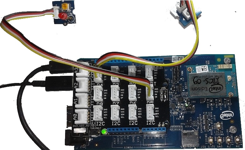
Figure 4.2 : Circuit For Mini Project 1- Switching LED with Button
Let's now see the coding. can you please try writting the code for the above logic?
I am sure you have written something like this
//listing: wrongLedSwitch.js
var mraa=require('mraa')

var ledPin=new mraa.Gpio(5);

ledPin.dir(mraa.DIR_OUT);

var buttonPin=new mraa.Gpio(4);

buttonPin.dir(mraa.DIR_IN);

loop();

function loop()

{

ledPin.write(buttonPin.read());

setTimeout(loop,1000);


}
just like read() is a method that returns intpu port's value. As we are considering Gpio, which is a digital port, the value would be either one or zero. So, you are trying to control the state of the LED based on the state of the button.
what is the problem? You must have observed, as you press the button, LED is turned on but as you release, it also becomes off. But we don't want that right? Once release, it should remain ON untill we press the button again. Then the LED should be off.
So, logically speaking, when the button state is 1 and LED state is o, LED state becomes 1. When button state is 1 and LED state is 1, LED state should become 0. Observe that we need a state variable here to implement the logic appropriately.
Also, you might have observed a latency in state change once the button is pressed. This is due to high delay in the loop. 100ms is a standard delay for looping. So, you need to change the delay to 100ms. Along with that, you need to introduce a state variable.
So we modify the code as bellow:
As you can see, instead of dealing with the state of the button, we are dealing with the transition. Whenever, there is a button state transition from 0 to 1, we are triggering the action.
Anything that causes a state change in putput port is known as triggers. In many IoT ecosyste you will hear this word trigger. A trigger can be a hardware trigger as in this case or a logical trigger like ( high temperatyre value or low light intensity). A trigger in IoT can be implemented locally or in the cloud.
// --> copy this code in main.js in your project
var mraa=require('mraa')
var ledPin=new mraa.Gpio(5);
ledPin.dir(mraa.DIR_OUT);

var buttonPin=new mraa.Gpio(4);
buttonPin.dir(mraa.DIR_IN);
var ledState=0;
var btnState=0;
loop();

function loop()

{

    var b=buttonPin.read();
    if(b==1 && ledState==0 && btnState==0)
        {
        ledState=1;
        ledPin.write(1);
        btnState=1;
        }
    else if(b==1 && ledState==1 && btnState==0)
        {
            ledPin.write(0);
            btnState=1;
            ledState=0;
        }
    if(b==0)
    {
     btnState=0;
    }

setTimeout(loop,100);

}
Now you can see, whenever we are pressing the button, the LED glows, remains ON till we again press the button as shown in animated figure 4.3.

Figure 4.3: LED Switching With Push Button
having been able to complete our first mini project, let us lern so IoT stuff. In the next mini project we will incorporate remote control of the same LED along with the switch that we have used here.
4.2 Mini Project 2: Remote Control with MqTT
4.2.1 MqTT

Figure 4.4 Basic Structure of MqTT Protocol
MqTT( figure 4.4) is a simple publish-subscribe protocol which in my opition is one of the best things to have happened for IoT.
A global MqTT broker allows the client programs to create a topic ( which is like a queue) in the server. A client program can be run on any device, including but not limited to Mobile, tablets, laptops, PC and of course an IoT device. Let us call an entity which runs a MqTT client as node9 nothing to do with node.js node). Plenty of Open source client libraries for MqTT is available in literally every programming language and stacks.
So, a node can publish binary data ( called message) into any topics. Topics can be heirarchially nested. For example We can create a topic as rupam, then rupam/home, then rupam/home/sensors and rupam/home/control, then rupam/home/control/locks and rupam/home/control/devices.
A node that subscribes to rupam will get every message published in either rupam or rupam/home or rupam/home/devices and so on.
Many nodes can subscribe to one or more topics. Whenever a node publishes a data in any of the topics, every node that have subscribed to the specific topic will receive the message from the broker asynchronously.
Further messages can be of two types: persistant and non-persistant. A persistant message will be retained by the broker even after it is pushed to subscribing nodes, where as non-persistant messages will be flushed.
So, a program that wants to use MqTT service needs to connect to broker, subscribe to topics and publish message into the topics.
In our current work context, all we need to do is publish message from our Android phone and write a node.js program in Intel Edison to subscribe to that topic. Whenever a message arrives through broker, analyze and take decision.
Important Resources:
Here are two free brokers for you that you can subscribe to enjoy IoT based messaging for FREE!!!!!
- iot.eclipse.org
- test.mosquitto.org
4.2.2 Working with MqTT in Intel Edison
MqTT is not included in core Node.js package. Therefore Edison doesn't support it out of the box. However the good news is that just like other Node.js environment, in Edison also, installing new Node.js package is painless and simple.
Installing external Node.js packages

Figure 4.5: Installing External Node.js package in Edison using npm
Just login to Edison using SSH tab of XDK. in the shell enter:
npm install mqtt
That's it. The package will be installed. You can now play around with MqTT. So, from our code we need to connect to a broker (we will use iot.eclipse.org here), subscribe to a topic( let's say rupam/control) , on message arrive event handler, analyze the message. If message is ON, switch on the LED, if OFF, turn off the LED. We also want to keep our switch based control intact. So we will modify ledSwitching.js listing of previous section and add MqTT feature.
Here is the MqTT part:
//////// MqTT Integration/////////
var mqtt    = require('mqtt');
var client  = mqtt.connect('mqtt://iot.eclipse.org');
client.subscribe('rupam/control/#')
client.handleMessage=function(packet,cb)
{
var payload = packet.payload.toString()
console.log(payload);
payload = payload.replace(/(\r\n|\n|\r)/gm,"");
if(payload=='ON')
    {
      ledState=1;
        ledPin.write(1);
    }
    if(payload=='OFF')
        {
             ledState=0;
        ledPin.write(0);
        }
    cb();
}
/////////////////////////////////
We create a mqtt client called mqtt, connect to the broker and subscribe to a channel called rupam/control. in the handleMessage() event handler we convert the message to string, remove extra blank characters and check for message text. We implement switching decision based on message.
Observe that we have created an function called cb() which stands for callback, and very importantly we call cb() again from handle message. This is a very important statement. If you forget to call cb() again from handleMessage(), then you will receive only one message :) rest of the messages will not trigger the handleMessage() function because client would have come out of it already. By calling the callback again we ensure that the client automatically go to listen mode again after it handles the first message.
Importantly, do not implement this chunk of code inside your loop. Because, if you do, it will keep creating a client instance for every looping instance, destroying the previous instance. So, you will never get a message because even before that message is arrived, listing client is reinitialized.
putting this back into our ledSwitching.js, here is the final code:
var mraa=require('mraa')
var ledPin=new mraa.Gpio(5);
ledPin.dir(mraa.DIR_OUT);

var buttonPin=new mraa.Gpio(4);
buttonPin.dir(mraa.DIR_IN);
var ledState=0;
var btnState=0;
//////// MqTT Integration/////////
var mqtt    = require('mqtt');
var client  = mqtt.connect('mqtt://iot.eclipse.org');
client.subscribe('rupam/control/#')
client.handleMessage=function(packet,cb)
{
var payload = packet.payload.toString()
console.log(payload);
payload = payload.replace(/(\r\n|\n|\r)/gm,"");
if(payload=='ON')
    {
      ledState=1;
        ledPin.write(1);
    }
    if(payload=='OFF')
        {
             ledState=0;
        ledPin.write(0);
        }
    cb();
}
/////////////////////////////////
loop();

function loop()

{

    var b=buttonPin.read();
    if(b==1 && ledState==0 && btnState==0)
        {
        ledState=1;
        ledPin.write(1);
        btnState=1;
        }
    else if(b==1 && ledState==1 && btnState==0)
        {
            ledPin.write(0);
            btnState=1;
            ledState=0;
        }
    if(b==0)
    {
     btnState=0;
    }

setTimeout(loop,100);

}
We want to control the led by sending ON and OFF message from our mobile. Again you can implement a simple MqTT Android client using Eclipse Paho Library
But, we are not really into Android. So instead of writing an App purely for this testing, we will use an existing MqTT client App from Google Play!
I particularly like and use MyMqtt app for my testing purpose.
Open the App, go to settings, connect to iot.eclipse.org, leave other defaults. Now go to publish section and in topic write rupam.control [ important:: Don't give a # while publishing]. Now Send ON or OFF to see your LED getting ON and OFF.
See the result in figure 4.6

Figure 4.6: Controlling LED over Internet using MqTT
Woohoo! You have just done your first "real IoT" program in Edison and controlled a LED remotely. Why don't you now try to control LED as well as Buzzer with commands like 'LED ON', 'LED OFF', 'BUZZ ON', 'BUZZ OFF'?
You can very well use small case as commands, but I prefer a capital command case to distinguish them from notmal text.
With that we come to an end of our Mini-Project 2 where we have learnt how to remote control components as well as the communication protocol between clients
In our next mini project, which will be the last of our learning projects, we will control the LED intensity as per room light intensity and provide details in a LCD. So, will will learn about PWM, LCD as two major things in next mini project as part of our learning experience.
4.3 Mini Project 3 : Controlling Light Intensity Based on Room Light
In this mini project, we will connect a LCD to display room light intensity, and change the intensity of the LED as well as the back color of the LCD as per the room light. We will keep our switching logic that we had developed in the previous sections. So by the end of this mini project, you would be able to switch your LED, along with controlling it's intensity. You will also learn about LCDs.
You need to add two extra components here: LCD and a Light Sensor. Can you rig up the circuit by glancing figure 3.5?
4.3.1 Working with LCD in Intel Edison
We will connect a LCD with any of the I2C ports ( the program will auto detect the port). We will first do some basic LCD coding. We will then implement pwm in 4.3.2 and then combine them into one entity in 4.3.3.

Figure 4.7: Connecting LCD with Intel Edison
Coding LCD is also quite simple. The LCD provided with Grove is in-fact a RGB back light 2x16 LCD. Which means that you can print messages in two lines, as well as change the background color of the LCD.
Let us create a simple LCD 'Hi Codeproject' program
// lcd.js
//// LCD part///////////

var LCD = require('jsupm_i2clcd');
var myLCD = new LCD.Jhd1313m1(6, 0x3E, 0x62);

myLCD.setColor(255,0,0);
myLCD.setCursor(0,0)
myLCD.write('Hi Codeproject')

myLCD.setCursor(1,0)
myLCD.write('Intel Edison')
////////////////////////
jsupm_i2clcd is a UPM i2c library for LCD that comes out of the box. So no new install. I have no idea of what Jhd1313m1(6, 0x3E, 0x62); is, buit seems needed for LCD initialization :(
Rest of the code is straight forward. First set back color with setColor(r,g,b) function. Set the cursor position using setCursor(row,col) . First we print 'hi codeproject' in 0th row, i.e. first line and then we set the cursor to second line ( row=1) and print 'Intel Edison'.
Here is how the result looks like:

Figure 4.8: Hello LCD with Intel Edison
We will now hook up a light sensor( also called LDR or light dependent resistor). Check out the next section for knowing LDR functioning
4.3.2 Working with LDR
I must tell at this stage that we are not going to use LDR in our project. So, I thought of by-passing this topic. However, in order to make your learning curve complete, I have put up this section. The objective of this section is purely to let you know about the working of sensors and have no bearning on our project. ( So, if you are interested only in our Biometric locker, you can skip this section. For first time learners, this is imporant). However, we shall cover some LCD best practices here. So, you would lose out if you skip this section!
As LDR is a Sensor, we will hook it up in any of the four available analog ports: A0-A3 ( refer figure 3.5)
Let's connect our LDR with A0 here. All you have to do is declare a ldrPin as new mraa.Aio(0). In loop, read the value of the sensor in a variable and display in LCD.
We will use write(),setCursor(row,col) and setColor(r,g,b) inside the loop and do the initialization at the top.
Let us modify ledSwitchingMqtt.js by adding sensor handling and lcd.js
var mraa=require('mraa')
var ledPin=new mraa.Gpio(5);
ledPin.dir(mraa.DIR_OUT);

var buttonPin=new mraa.Gpio(4);
buttonPin.dir(mraa.DIR_IN);
var ledState=0;
var btnState=0;
// LDR Part//////////////
var ldrPin=new mraa.Aio(0);
// no need for initializing dir for Aio as Aio pins are only input type
//// LCD part///////////

var LCD = require('jsupm_i2clcd');
var myLCD = new LCD.Jhd1313m1(6, 0x3E, 0x62);
myLCD.setColor(255,0,0);
myLCD.setCursor(0,0)
myLCD.write('Hi Codeproject')
myLCD.setCursor(1,0)
//myLCD.write('Intel Edison')
// we will use second line to print light value
////////////////////////
//////// MqTT Integration/////////
var mqtt    = require('mqtt');
var client  = mqtt.connect('mqtt://iot.eclipse.org');
client.subscribe('rupam/control/#')
client.handleMessage=function(packet,cb)
{
var payload = packet.payload.toString()
console.log(payload);
payload = payload.replace(/(\r\n|\n|\r)/gm,"");
if(payload=='ON')
    {
      ledState=1;
        ledPin.write(1);
    }
    if(payload=='OFF')
        {
             ledState=0;
        ledPin.write(0);
        }
    cb();
}
/////////////////////////////////
loop();

function loop()

{

    var b=buttonPin.read();
    // LDR part/////////
    myLCD.setCursor(1,0);
    var ldrVal=ldrPin.read();
    // convert the value into percentage
    var pc=ldrVal*100.0/1024.0;
    pc=Math.floor(pc * 100) / 100;
    myLCD.write('Light='+pc+' %')
    /////////////////////
    if(b==1 && ledState==0 && btnState==0)
        {
        ledState=1;
        ledPin.write(1);
        btnState=1;
        }
    else if(b==1 && ledState==1 && btnState==0)
        {
            ledPin.write(0);
            btnState=1;
            ledState=0;
        }
    if(b==0)
    {
     btnState=0;
    }

setTimeout(loop,100);

}
Let us analyze the LDR part:
// LDR part/////////
    myLCD.setCursor(1,0);
    var ldrVal=ldrPin.read();
    // convert the value into percentage
    var pc=ldrVal*100.0/1024.0;
    pc=Math.floor(pc * 100) / 100;
    myLCD.write('Light='+pc+' %')
    /////////////////////
Analog ports in Arduino compatible devices are internally hooked to 10 bit A2D converters. So read() function on analog pin returns a 10 bit digital equivalent of the sensor value. Maximum value is 1024. After reading light intensity, we are converting into percentage. Math.floor() is used to convert the number to 2-place decimal only.
Try the example by commenting out this line.
observe we are calling myLCD.setCursor() every time in loop. Because, by default the cursor position will be placed at the end of the last string.
Try the example by commenting out the setCursor() call.
Here is how the circuit and the display looks like:

Figure 4.9 LDR Circuit and Result Displayed in LCD
So, in this section we learnt
- how to efficiently use LCD's 16 character in a line to efficiently display information
- how to work with sensors( LDR in particular) and display it's value in LCD
In next section we will learn about controlling our LED intensity depending upon light value.
4.3.3 PWM- Controlling Light Intensity based on LDR value
The first question that obviously comes to reader's mind is "what has a light intensity to do with a locker"? Well, actually nothing direct. But, we will be using servo motor in our project for controlling the lock( which will be covered later). Servo control is based on PWM. Even though we will use a library for motor control which will not expose PWM low level calls directly, it is always good to understand how to work with PWM so that you can in future write your own Servo control logic based on raw PWM calls.
In the context of the current tutorial, this section also helps in performing switching and PWM control through local switch as well as from remote using MqTT.
Some of the PWM basics can be found in my Arduino Basic Tutorial's PWM section. So, we will bypass the theory part and just take a simple summery from that tutorial.
Pulse Width Modulation or PWM is a way of controlling current through a load ( like motor/ light etc) by varying the duty cycle of the pulse. A pwm signal with duty cycle 70% means that the motor connected with the associated pin will be rotated with a speed of 70% of it's max.
Here is the code:
var mraa=require('mraa')
/*---------- Uncomment for Plain Switching *****/
//var ledPin=new mraa.Gpio(5);
//ledPin.dir(mraa.DIR_OUT);
/*---------- Uncomment for Plain Switching *****/

//---- PWM---------//
var ledPin=new mraa.Pwm(5);
ledPin.enable(true);
//---------------------//

var buttonPin=new mraa.Gpio(4);
buttonPin.dir(mraa.DIR_IN);
var ledState=0;
var btnState=0;
// LDR Part//////////////
var ldrPin=new mraa.Aio(0);
// no need for initializing dir for Aio as Aio pins are only input type
//// LCD part///////////

var LCD = require('jsupm_i2clcd');
var myLCD = new LCD.Jhd1313m1(6, 0x3E, 0x62);
myLCD.setColor(0,255,0);
myLCD.setCursor(0,0)
myLCD.write('Hi Codeproject')
myLCD.setCursor(1,0)
//myLCD.write('Intel Edison')
// we will use second line to print light value
////////////////////////
//////// MqTT Integration/////////
var mqtt    = require('mqtt');
var client  = mqtt.connect('mqtt://iot.eclipse.org');
client.subscribe('rupam/control/#')
client.handleMessage=function(packet,cb)
{
var payload = packet.payload.toString()
console.log(payload);
payload = payload.replace(/(\r\n|\n|\r)/gm,"");
if(payload=='ON')
    {
        on();
    }
    if(payload=='OFF')
        {
             off();
        }
    cb();
}
/////////////////////////////////
loop();
var desiredLight=1;
function on()
{
    ledState=1;
        //------ Uncomment for plain switching///////

        //ledPin.write(1);
        //-------------------------------//

        // PWM---------//

    console.log(desiredLight);
        ledPin.write(desiredLight);
        /////////////////
        /////////////////
}
function off()
{
    ledState=0;
             // For pwm only////////
            ledPin.write(0);


}
var t=0;
function loop()

{

    t++;

    var b=buttonPin.read();
    // LDR part/////////
    myLCD.setCursor(1,0);
    var ldrVal=ldrPin.read();
    // convert the value into percentage
    var pc=ldrVal*100.0/1024.0;
    pc=Math.floor(pc * 100) / 100;
    myLCD.write('Light='+pc+' %')
    desiredLight=(100-pc)/300;
    if(ledState==1)
        {
            // if light is on adjust intensity every 5 sec
            if(t>=50)
                {

                    ledPin.write(desiredLight);
                    t=0;
                }
        }

    /////////////////////
    if(b==1 && ledState==0 && btnState==0)
        {
        on();

        btnState=1;
        }
    else if(b==1 && ledState==1 && btnState==0)
        {
            off();
            btnState=1;
        }
    if(b==0)
    {
     btnState=0;
    }

setTimeout(loop,100);

}
Observe, for PWM, we are declaring ledPin as mraa.pwm(5). Calling enable(true) activates PWM mode.
//---- PWM---------//

var ledPin=new mraa.Pwm(5);

ledPin.enable(true); //---------------------//
Also note that, we have separated switching logic as on() and off() functions. write(0) is turning off logic for plain digital pins as well as in pwm mode.
Interestingly in the on() function we have used write(desiredLight) instead of write(1) which we used for plain switching.
desiredLight is a global variable, whose value changes in the loop() function right after calculating light percentage. pwmPin.write(duty_cycle_in_decimal) expects you to specify the desired duty cycle in fraction ( eg: .77 for 77% duty cycle, .63 for 63% duty cycle and so on). So we calculated desiredLight as a fraction by subtracting light percent pc from 100 and dividing that by 100 for percentage to fraction conversion.
So, if room light is 80%, we will be glowing our led with only 20% intensity, so desiredLight will be .2 .
Also, note that we are actually changing the intensity value in every 5 seconds when the light is on.
Execute this program. What you see?
You will notice that everything is working fine, just that after switching off, LED is not entirely turned off. It is glowing with very little intensity as shown in figure 4.10.

Figure 4.10: LED glowing even while it is off in PWM mode
This is because, in pwm a signal pulse is sent to keep the pwm pin active. The pulse width of no pulse can be zero, so the light never actually turns off.
But, don't worry. This problem can be overcome by calling enable(false) after write(0) in off() and calling enable(true) before write(desiredLight) in off() function. What if you change the order? If you call enable(false) before write(0), that pwm duty cycle of 0 will never be written and LED will not at all turn off.
So, our on and off functions are now modified as below.
function on()
{
    ledState=1;
        //------ Uncomment for plain switching///////

        //ledPin.write(1);
        //-------------------------------//

        // PWM---------//

    console.log(desiredLight);
        ledPin.enable(true);
        ledPin.write(desiredLight);
        /////////////////
        /////////////////
}
function off()
{
    ledState=0;
             // For pwm only////////
            ledPin.write(0);
            ledPin.enable(false);
          /////////////


}
When you are enabling the pwm from on() function, you must not do it at the time of declaration. I do not know why, by enabling pwm multiple times fails to write the percentage value :(
//---- PWM---------//
var ledPin=new mraa.Pwm(5);
//ledPin.enable(true); don't call it here--> enable it from on function
//---------------------//
4.3.4 Servo Control
I had earlier planned to to include a separate sub section for Servo control and explain it directly in our IoT device app. But, my wife suggested that Servos may be needed in many other projects like robotics. So creating a basic working of Servo with Intel Edison will be good. As you know, we the men often are weak towards lady's suggestions. So here is the sub section demanded strongly by my wife.
Essentially you need to hook the servo with the PWM port like D5/D6 as you have done for LED intensity control.
We need two npm libraries for working with Servos. johney-5 and edison-io. johney-5 is particularly popular for robotics DIY in many platforms including R-Pi. Add them into your code with require function of Node.js
var five = require("johnny-five");
var Edison = require("edison-io");
What we will try to do here is connect the servo with D5 and a button in D4( yes, remove that LED and keep it in place in your Grove box). When we press the button once, Servo should move clockwise ( once) then again when we press the button, it should move 90' anticlockwise to come to it's actual position.
So, essentially we will be controlling the angle of the Servo's position. let's a 0' current position and 90' the other position. Let us define a global variable angle to keep track of current value.
Initially angle is 0.
var angle=0;
let us define a variable called sw ( short for switch) for defining button state.
var mraa=require('mraa');
var sw=new mraa.Gpio(4);

sw.dir(mraa.DIR_IN);
Let's initialize johney-5 and set the servo angle to 0.
var board = new five.Board({
  io: new Edison()
});
  var servo = new five.Servo({
      pin:5
  });
  servo.to(0);
servo.to(ANGLE) can be used to set Servo's angle to ANGLE angle needs to be specified in degree. So 90', 45' are valid Servo angles.
This is extremely simple from this point on. You already know the switching logic from your LED Controlling with Button example. All you have to do now is replace ledPin.write(1) with servo.to(90) and ledPin.write(0) with servo.to(0). You also need to replace ledState=1 with angle=90 and ledState=0 with angle=0. In the comparision logic instead of comparing with ledState, compare angle.
function loop()

{

    var b=sw.read();
    if(b==1 && angle==0 && btnState==0)
        {
        angle=90;
        servo.to(90);
        btnState=1;
        }
    else if(b==1 && ledState==1 && btnState==0)
        {
            servo.to(0);
            btnState=1;
            angle=0;
        }
    if(b==0)
    {
     btnState=0;
    }

setTimeout(loop,100);

}
Didn't I tell you that working with Node.js and Intel Edison is really simple? I am not adding any snaps of this experiment because I am now confident that you don't need an illustration for this experiment.
With that we come to an end of our learning process of Intel Edison basic hardware. There are plenty more to learn like accelerometer, vibration sensor and so on which can not be covered in this article.
I included this section for beginners in Edison to get comfortable with coding so that we we start with our project, you are comfortable and can perform the steps yourself.
Let us recall things we learnt in this chapter before starting the next chapter where we will be configuring Web Cam and Audio as integral part of our project.
Chapter Summery: What we learnt
- How to implement input-output embedded program logic in Node.js
- How to design hardware easily with Grove connectors and Grove Shield
- Design process
- We performed three live mini projects as part of our learning
- We learnt about MqTT, an easy and universal message exchange protocol for IoT
- We controlled LED remotely using our mobile
- We learnt how to use LCD efficiently
- Use of PWM and using PWM for both switching as well as intensity control
- How to use npm from XDK ssh in Edison to install externall Node.js libraries.
You can download all the codes in three mini projects as a single Intel XDK project from following Link. ( It includes package.json which automatically installs all the dependencies like MqTT. So once you import this project to your XDK, you wouldn't have to worry about installing npm separately.
Download all Mini project code as single XDK project
5. Setting up Audio and Web Cam in Intel Edison
Finally, after getting a foot hold on Intel Edison and doing three confidence booster projects, you are now ready to leap ahead and do some non-hardware media related operation with Intel Edison. As the name of the project suggests we are going to use two modalities for our project: Face and voice. Face recognition needs you to capture images from WebCam and Voice Verification needs voice capture from input Audio devices. Therefore the first step is to configure them.
Unfortunately there is no plug and play ways of doing it. Both camera and Voice needs to be configured first before you are able to work with them.
I am putting Voice and Camera configuration as a separate chapter and abstracted it from the core project development chapter to present it as a resource. If your own idea includes working with either or both of camera and voice, then you can use this chapter as a reference for setting up.
This chapter will have two sub topics:
- Configuring Web Camera with Intel Edison
- Configuring Audio with Intel Edison
Let us get started with Configuring camera. Before that, you may want to have a close look at our hardware requirement section to know what camera is needed. Non-UVC compatible camera will not work with Edison.
Also note that Web camera has to be connected to Edison via it's host USB port. So, Edison has to drive the current for the camera. Therefore a 12v supply is mandatory for the device. Please refer figure 3.2 for more details. I advise you to stick to Official Edison 12v power supply for working with Audio and Video in Edison.
5.1 Setting Up Web Cam with Intel Edison
I am using a Creative Sensz3d camera because I got it from Intel during Perceptual computing Challenge(free!) and it has got a nice Microphone array for capturing high quality Audio. You can go for any UVC compatible camera with Microphone.
If you have worked with Linux, most of the releases has nice "sudo apt-get install" kind of stuff which makes the life easy in Linux platform. However, Yocto doesn't have any such package manager out of the box. But fortunately Alex has created an awesome package manager for Edison called opkg which is unofficially the official package manager in Intel Edison. For complete 5.1 section , please login to Edison from PuTTY using SSH. ( because a) you need internet connection and b) you need to open multiple shells to install and validate)
Step 1: Driver Check
Web camera needs Web Cam drivers. First check if you have uvc camera driver installed or not by following command
find /lib/modules/* -name 'uvc'
If it shows an installed driver like following figure, then you are all set.

Figure 5.1 UVC driver detection in Edison
Step 2: Opkg Update
update the opkg first.
vi /etc/opkg/base-feeds.conf
and add following lines with the configuration file
src/gz all http://repo.opkg.net/edison/repo/all
src/gz edison http://repo.opkg.net/edison/repo/edison
src/gz core2-32 http://repo.opkg.net/edison/repo/core2-32
Press Esc : wq to save and come out of the Editor
now
opkg update
Step 4: Driver Installation ( if Step 1 fails, i.e. no driver is installed)
Now download and install the uvc driver using opkg
opkg install kernel-module-uvcvideo
You may need to reboot your Edison board after uvc driver installation.
Step 5: Web Camera detection
Plug in your camera and reboot the device ( camera driver is loaded only at the time of boot. So, either you connect the camera and boot or if the device is already booted, use reboot).
Now give following command.
lsmod | grep uvc
If the result shows uvc module then your camera is detected and it's driver is loaded by Edison
When web cam is installed and plugged in, Edison creates a node in /dev. So, check that video0 node is created by following command
ls -l /dev/video0
The result of this complete stage is shown in figure 5.2

Figure 5.2 Detecting Webcam in Edison
Step 6: Install fswebcam for taking pictures from camera
opkg install fswebcam
Step 7: Taking your beautiful photo from Edison
fswebcam test.png
Photo captured by Web camera will be stored as test.png in root folder. Download test.png from WinScp.
What you see?
A, not so good blur image? That is because fswebcam queries the device, even before the camera is ready. So capture 10 frames to get a good quality photo.
fswebcam --frame 10 good-img.png

Figure 5.3 Capturing images through web camera in Intel Edison
Congratulations for getting web camera to work with Edison. This is another small step towards the giant leap you are going to take.
5.2 Setting up Audio
In many of the applications, you may need to stream audio. For suc applications, a bluetooth audio device is essential. We are using audio input here to capture the voice of the person. So, I will stick to Audio input configuration in this section and omit the audio output and streaming part. Our camera has a microphone. The first step is to detect this microphone, then to set it up as default audio input device and finally setting up the configuration like audio volume, sampling rate and so on.
I advise you to download and read this official Intel Edison Audio Setup guide.
Intel Edison provides an utility called arecord out of the box. You jsut need to configure it.
Step1 : Detecting your recording device
type following command in PuTTY
arecord -l
It should show you list of all the devices as in figure 5.4

Figure 5.4 List of Recording devices generated by arecord -l command
Identify and mark the card number associated with your device. It is card 2 in my case
Step 2: Setting your audio input device as default capture device
Once you have detected your audio device, the next task is to set arecor's default audio as this device.
vi .asoundrc
and enter following:
pcm. !default

{

type hw

card 2

device 0

}
Esc :wq to save and exit. That's it. Your Audio recording properties are set.
Step 3 Recording Audio
Having set your default recording device, it is finally time to record audio. Use arecord's command line utility to record the audio
arecord -f cd test.wav
-f cd forces arecord to use cd quality ( 44khz) for recording.
It will start recording. In order to stop the record, just use ctrl+c. Again you can download the recorded file using WinSCP and analyze.
The result of me speaking "codeproject is a great site and I love codeproject" can be see in figure 5.5

5.5 Result wav file generated through arecord command line recording utility
In case you are wondering which software is used for displaying the wavform, it is Audacity which is a great tool for creating and editing sound.
Step 4: Configuring Audio Properties ( Optional)
Voice verification needs a clear audio. The voice amplitude must be good. The default audio property may not always be ideal. If you are not getting a good sound quality, you can bring up command line graphical audio property setting utility by generating command
alsamixer
Once the Utility is displayed, press F6 to select the sound card as shown in figure 5.6

Figure 5.6 : Sound card selection in alsamixer
Now use up and down arrow keys in your keyboard to set up the ideal gain for the recording devices.

Figure 5.7: Recording property control
That's it. You are now able to record audio and change audio settings right in your IoT device.
With this, we come to an end of our training series in Intel Edison. It is time to go to our next section for designing and creating our project.
But before we end, like other chapters, let us recapitulate what we have learnt in this chapter:
- opkg upfate and installing kernel and driver modules using opkg
- setting up web cam
- capturing picture through web camera in Edison
- Configuring Audio device
- Recording Audio through Audio device
- Setting audio recording properties.
With this we are now ready to create our Biometric Locker. In Part 2 of this article we will cover the making of our prototype in great details. Cheer up for your efforts and completion of learning IoT ecosystem with Intel Edison.
Part B : Let's Make
6. System Design
In this chapter we will mainly focus on various issues leading to our product. We will discuss about design, the overall flow of the project, creating our prototype. We will also discuss about Face recognition and voice verification and workflow of both of these processes. Let's first understand the architecture of the project first which I have elaborated in the next section.
6.1 System Architecture

Figure 6.1 System Architecture
Our locker is powered by Intel Edison. Locker here is essentially a box with a locking mechanism. We are going to use servo motor as a lock. The locker will have a LCD for showing user the current process and any other instructions. The button is for opening and closing the lock. For closing the lock, no authentication is required but for opening the lock user authentication is needed.
The Locker should also have a camera+ mic combo connected with Intel Edison USB host port.
Now, we need a client GUI based form for registration where user can enter essential details like username, text password and any other information. As, Edison doesn't have keyboard and GUI support, this part needs to be performed at a different edge device like mobile or PC. We often call such apps as "Companion App" in a mobile realm. For this particular prototype we would go with a PC app with my favorite C#.
The Client PC APP takes care of user registration process. We will also use Text to Speech here and would use PC's Speakers for generating the instructions. At this moment, this will be single user/PC based application.
The client app would create a user account at the cloud. We are going to use Knurld's user management system to register user account. Detailed workflow of Knurld will be explained later as a separate sub section.
At the time of registration, the PC app will ask the user to speak certain voice phrases. User's voice sample will be collected and will be stored in the cloud and voice features will be extracted and stored with Knurld for the specific registered user.
During registration, PC app will also capture user's face and will register it with Microsoft's Oxford AI Apis , part of Microsoft's cognitive services.
The face recognition api returns a user ID when face is registered. This face user ID and voice user ID is sent to Locker device via MqTT.
When user presses the button in the locker, Intel Edison first captures photo of the user and store the photo in the cloud and send the link of the photo and the face user ID for verification to Oxford AI. If face is verified, user is asked to speak some given sample phrases. This is recorded as an audio file and is stored in the cloud. The Voice registration ID and this verification audio link is sent to knurld for verification. If the verification is successfull, then the lock is opened. Once user clicks the button again, the lock is closed.
Important Note:
As most of the cloud based biometric service providers accepts a link to the sample trait, we need to also use storage as a service as not all of the service providers offer a storage service. Therefore we are going to use Dropbox Apis for storage service. Recorded audio and captured photo will be stored in DropBox and their link will be obtained. Registration and verification services will be passing these links to respective end points.
So we also need a Dropbox account along with an account with Microsoft and Knurld. We shall take a deeper look at each of these services and their end points in later part of these chapter as separate sub sections.
So, let's get started and let us fabricate our locker first.
At this stage, i would also want to share with you the service structure of the project. The entire Locker needs several API calls to and from to Dropbox, Oxford AI and Knurld from both PcApp as well as from Locker. So it is important to understand the entire process before we can focus on our coding strategy. Figure 6.2 provides the complete call-service-API endpoint structure.

6.2 Reference Sequence diagram of the project
This Diagram is enough to explain you the kind of complicated API call structure we are needed to build for our project. For those of you who are more comfortable with algorithm than the diagrams, here is algorithm for you.
Detailed flow of the Biometric Locker
PcApp ->user : username,password ?
user -> PcApp : username,password,gender
PcApp -> Knurld : user exists?, AppModel
alt exists
PcApp -> user : change credential
else Success
Knurld -> PcApp : UserId
PcApp -> user : registration success
PcApp -> Knurld : enroll voice, UserID, AppModel
Knurld -> PcApp : Phrases, RegistrationID
PcApp -> user : Speak phrases
user -> PcApp : Recorded audio( audio.wav)
PcApp -> Dropbox : store audio.wav
Dropbox -> PcApp : Done
PcApp -> Dropbox : give link of audio.wav
Dropbox -> PcApp : Audio_url
PcApp -> Knurld : Analyze( AppModel, Audio_Url, RegistrationID)
Knurld -> PcApp : timing.json
PcApp -> Knurld : Enroll(AudioUrl, phrases_with_timing.json,registrationId, UserID,AppModel)
Knurld -> PcApp : Enroll Message
alt Success
PcApp -> user : Voice enrolled
PcApp -> Locker : AppModel, UserID
Locker -> Locker : Store AppModel,UserID
PcApp -> user : Photo capture
user -> PcApp : phto through camera photo.jpg
PcApp -> Dropbox : Store phto.jpg
Dropbox -> PcApp : photo.jpg stored
PcApp -> Dropbox : give link of photo.jpg
Dropbox -> PcApp : photo_url
PcApp -> OxfordAI : faceDetect(photo_url)
OxfordAI -> PcApp : faceID
PcApp -> Locker : store faceId
Locker -> Locker :faceId stored
else fail
PcApp -> user: Enrollment failed
end

end
user -> Locker : Open Lock
Locker -> user : "smile please"
Locker-> Locker : Capture photo as photo.jpg
Locker -> user : photo captured
Locker -> Dropbox : store photo.jpg
Dropbox -> Locker : photo.jpg stored
Locker -> Dropbox: give url of photo.jpg
Dropbox -> Locker : Photo_Url
Locker -> OxfordAI : Verify ( faceId,Photo_url)
alt success
Locker -> user : "face verified"
Locker -> Knurld : Verify(userId, AppModel)
Knurld -> Locker : VerificationId, Phrases
Locker -> user : "Speak phrases"
Locker -> Locker : Record audio as audio.was
Locker -> user : Audio recorded
Locker -> Dropbox : Store audio.wav
Dropbox -> Locker : Audio.wav stored
Locker -> Dropbox : give url of audio.wav
Dropbox -> Locker: Audio_url
Locker -> Knurld : Analyze(AppModel,verificationID,Audio_url)
Knurld -> Locker : timing.json
Locker -> Knurld : verify(phrases_with_timing.json, AppModel,UserId, VerificationID)
Knurld -> Locker : Verification result
alt Success
Locker -> user : "User Authenticated"
Locker -> Locker : LOCK_OPEN
else
Locker -> user : "failed"
Locker -> Locker : BUZZER
end
end
We shall come back to this reference structure when we dig into details of all of Dropbox, Knurld and Oxford AI.
Having pretty much detailed flow structure, let us first create our locker and then we will come back to the software part again.
6.2 Fabrication
We first need a box which would be used as Locker. If you have access to 3D printer, you are most welcomed to design a great box and 3D print it. Unfortunately I don't have any such access. So I use a cardboard box which essentially carried a memento I received in Intel Software innovator meet recently.
Figure 6.3 Shows the proto of the locker box.

The connection details are as presented in figure 6.4

Figure 6.4 Connection Details of Biometric Locker
Now once you have connected the components with Grove Shield and Edison, we need to fix the components on this box to get a complete independent box.
First, you need to put the Edison board. mark the points where Edison board stands are there as in Figure 6.5, drill the points, or make holes using screws. Finally push the Edison board along with their stands in the four holes as shown in figure 6.5

Figure 6.5 Inserting the Edison board into driolled slots in the Locker Box
Glue rest of the components on the board as shown in figure 6.6

Figure 6.6 : Glue and Place the connected components on Locker
Finally when done, our locker looks something as figure 6.7 and 6.8.

Figure 6.7 Isometic View of the Locker

Figure 6.8: Top View of the Locker
You can see that we have attached the Servo motor at the side such that it keeps the lock closed. With that, we have completed the fabrication of our locker. If you have succeeded in emulating the fabrication, cheer yourself. Because, you have come a long way from being a novice to an IoT professional having a prototype of a model.
Now we shall take deep look into voice recognition system with Knurld.
6.3 Voice Recognition With Knurld
6.3.1 Understanding Voice Recognition
Even though Knurld is a Cloud based voice verification service provider and you don't really need to understand the nitty gritty of the voice biometric process, it is always good to have a basic idea about the system to use it effectively. Let's understand a basic Voice Biometric system in order for us to use Knurld's services more effectively.
A Biometric System in general is divided into two phases: Enrollment nd Verification. Enrollment is is similar to user registration process that we see in our common day to day mobile and web based applications. In this stage a user details is collected by the system. Enrollment also includes an extra entity which is the biometric sample of the user. In case of voice biometric, it is voice sample of the user and in case of face biometric, it is face photo of the user.
A voice biometric system can be typically of two types: text dependent system and text independent system. A text dependent system requires that user speaks the same set of phrases that he used for enrollment. A text independent system on the other hand is independent of what user speaks, it relies on the inherent properties of the user voice like pitch.
A text independent system is not really scalable as it is extremely difficult to create sets of unique features that identifies one user from the other.
text dependent system can be further divided into two types: closed set v/s open set system, A closed set system is where user needs to speak phrases from a selected list where as in open set, user can chose sets of words he wants to speak.
In an open set system, as user is at liberty of picking up any words and because each word have different phonetics, modelling the features for identifying each user independently is extremely difficult. So, off late closed set systems are being widely accepted ones.
A voice authentication scheme can further be divided into two types : verification and identification. An identification process is one, where no reference sample is provided to system for matching. System has to match the features of the test sample with the features of all the registered user to find out which user's voice is identical. This system is mainly of forensic interest and is used mainly as a biometric search tool. One example of an identification system ( face not voice) is facebook's face search technique where soon as you upload some photos it gives you hints about the users present in the photo.
Knurld is Closed set, Voice Verification based voice biometric system.
Any biometric system's core is feature extraction process. A feature is a high level descriptor of the biometric trait ( like Iris, face, voice, fingerprint). Different algorithms are adopted by different biometrics to represent the trait as feature vectors.In case of Voice Biometric, the most common features as cepstral features. Any biometric system adopts a preprocessing step prior to feature extraction. The two most important preprocessing steps for a voice biometric are: Silence removal and noise reduction. The voice sample is low pass filtered first to remove noise. Then using temporal segmentation technique, spoken phrases are separated.
Cepstral features from these are extracted and stored in database or used for matching.
Voice verification system in turn can be either model based or feature based. A feature based system is one where user's phrase feature vectors are compared with the reference feature vectors. however, in a model based system, random order of phrases in the reference for the user is created at the time of verification. User needs to speak the phrases in exact same order. System checks not only for the features of each of the phrases, but also finds out if the phrases are being spoken in a given order. This method claims to remove the possibility of forgery through pre-recorded voices as user would not know what phrase order is presented to him during verification stage.
Knurld as such adopts a model based system.
Even though company claims to have a cutting edge preprocessing stage inplace to eliminate most common noises, let me tell you there is no replacement for a good quality audio capture if you want to have an efficient voice biometric system.
So, we need to learn about user registration, voice analysis, voice enrollment, voice verification with Knurld
6.3.2 Knurld API and Services
Step1: Register and obtain developer ID
You need to first register a developer account with Knurld from this register link. When you are successfully registered with Knurld, you will sent an Email from the company specifying your developer ID and oAuth token as seen below.

Figure 6.9 Knurld Welcome mail with developer ID and token
You need to keep it safe and copy it into some files.
Step 2: Obtain Client Id and Client Secret
once you are registeres as developer, login to developer home. There you will find a link to "My Apis". When you click on "My Apis" you get a hyperlink "Knurld.io Advanced Speech technology Api". Click on that link and you will see your client ID and Client secret.

Figure 6.10 Obtaining client_id and client_secret of Kurld
So, you need developer id, client_id, client_secret to develop end to end voice based authentication using Knurld
Step 3: Authorization: Obtaining oAuth token
You need to pass client_id and client_secret to oAuth end point of Knurld to obtain an oAuth access token. oAcuth token and developer_id will be needed to make calls to other Apis.
You can visit Knurld's interactive developer resource to test the APIs without writing a single line of code. Migrate to Authorization and enter your client_id and client_secret that you got in step-2.
You can also see the API end point details in the interactive part which is as follows
curl -X POST "https://api.knurld.io/oauth/client_credential/accesstoken?grant_type=client_credentials" \
  -H "Content-Type: application/x-www-form-urlencoded" \
  -d "client_id=$CLIENT_ID" \
  -d "client_secret=$CLIENT_SECRET"
So, from any programming language you can take a httpClient( almost all languages has their heet client), create a POST request to the end point, specify content type and put client_id and client_secret as parameters.
following figure 6.11 shows the HTTP 200 result of the API call and obtained access token.

Figure 6.11 Knurld Authorization: Obtain Access token from client_id and client_secret
As mentioned in section 6.3.1, Knurld is a closed-set, model based, voice verification voice biometric. So you need to setup an app model with at least three phrases from the list of supported phrases by Knurld. For creating App model, go to their App model section of the interactivce api explorer again.
This is the curl request:
curl -X POST "https://api.knurld.io/v1/app-models" \
    -H "Content-Type: application/json"  \
    -H "Authorization: Bearer $AUTH_TOKEN"  \
    -H "Developer-Id: Bearer: $DEVELOPER_ID"  \
    -d ‘{“vocabulary”:[“$PHRASE1”, “$PHRASE2”, “$PHRASE3”],"verificationLength":$VERIFICATION_LENGTH}’
And here is the call to Api from the interactive demo

Figure 6.12: Creating App Model From Interactive Api Explorer
Very Very important:
The developer id( the one that you got through gmail) must be specified with a colon after bearer ( Bearer:), where as access token ( the one that you got by calling Authorization end point through your client_id and client_secret) must be specified with (Bearer ) i.e. Bearer SPACE ( no : COLON here). If you miss this important point, you will not be able to make any API calls from here on.
Save the App model i.e. "https://..." into some file as your App model. All your Enrollment and Verification will be based on this model. Observe the phrases we passed for creating the App model: They are: London, paris and Circle". You can pick any sets of words from Knurld's allowed words as mentioned above.
Step 5: Test all the features from interactive website
Login to Knurld's Online javascript based demo of their entire process flow.
Knurld's Online Comple App Process flow demo login

Figure 6.13: Live Demo site showing the App model we created in step 4
You can explore all the options in the demo site to get comfortable with the APIs and process flow.
6.3.3 Knurld Process flow
We have already learnt a bit of our coding strategy from 6.3.2. We have understood the process flow for authorization and creating app model. creating a consumer is also on the similar lines. But the verification and enrollment process needs detailed understanding because they are not a single API call, but rather set of APIs that needs to be called in order by chaining the output of one with another.
Enrollment is a multi step process which is explained in steps here:
Step 1 Create Enrollment
Let's analyze the curl API call
curl -X POST    'https://api.knurld.io/v1/enrollments' \
  -H "Authorization: Bearer $AUTH_TOKEN" \
  -H "Developer-Id: Bearer: $DEV_TOKEN" \
  -d '{ "consumer": "https://api.knurld.io/v1/consumers/$CONSUMER_ID", \
        "application": "https://api.knurld.io/v1/app-models/$APPLICATION_ID" }'
You need to pass Bearer oAuth token and Bearer: Developer-Id as header to post request to endpoint https://api.knurld.io/v1/enrollments
The content-type must be set to application/json
In the data field of the request you need to pass a json data with consumer url you obtained when you created consumer. It will return an enrollment_url and instructions as JSON object. In instruction, the phrases and number of times they are to be spoken by the user is mentioned. The response will contain the complete url as /v1/enrollments/xyz
where xyz is the enrollment task id. Save this url. This needs to be called at the step4.
{
   "href": "https://api.knurld.io/v1/enrollments/jdjfkjdskjfweo10280948921"
}
Step 2: Submit Analysis
Even though, the second step in the API reference is given as populating enrollment, if you observe the API which we will cover in step 3, you will see that the call needs a payload field "phrase": , "Start","Stop". What is this payload?
Basically, this is a payload that specifies which word starts at what time instance in your audio and ends at what time instance? How do you get it? for that you need to call analysis.
Analysis supports two types: Multi-part form data, end-point analysis by url. As, final verification and enrollment doesn't support multi part form data and only accepts url, we will stick to url only.
curl -X POST “https://api.knurld.io/v1/endpointAnalysis/url” \
  -H "Authorization: $AUTH_TOKEN"  \
  -H "Developer-Id: $DEVELOPER_ID"  \
  -H "Content-Type: application/json"  \
  -d '{ "audioUrl":<URL_TO_FILE>, "words":<int>}'
While calling analysis for enrollment "words" will be 9 as all the three phrases are to be spoken three times each by the user. audioUrl is the downloadable remote location where your audio is stored.
So, you need to record the audio from microphone, save it as a wav file ( only .wav format is supported as of now), push to a cloud storage service, acquire the URL and pass that to analysis service.
This is the very reason we need a Dropbox integration with both our PC app as well as our IoT device app.
The problem with Knurld is that it doesn't return the phrases and their temporal location from this call. It just returns a task name.
{
  "taskName": "f25b31b1ab3d2400cada5dead8c7b256",
  "taskStatus": "started"
}
You need to now call Get Analysis end point to finally get the phrases
Step 3: Get Analysis
curl -X GET “https://api.knurld.io/v1/endpointAnalysis/$TASK_NAME” \
  -H "Authorization: $AUTH_TOKEN"  \
  -H "Developer-Id: $DEVELOPER_ID"
In endPointAnalysis, you can see a variable called $TASK_NAME here you need to pass taskName value that you had obtained from Submit Analysis step.
This returns a JSON object as bellow.
{
  "taskName": "f25b31b1ab3d2400cada5dead8c7b256",
  "taskStatus": "completed",
  "intervals": [
    {
      "start": 2576,
      "stop": 3360
    },
    {
      "start": 3856,
      "stop": 4512
    },
    {
      "start": 5040,
      "stop": 5568
    }
  ]
}
For Enrollment, there will 9 such array elements, for verification there will be three elements.
Observe carefully that this JSON array only gives start and stop intervals of the phrases and not the phrases themselves. But the next step, which is submitting analysis result for enrollment, needs an array with element phrase, start and stop. So, here in this step you have to obtain the result, parse them, append the phrases, create a new JSON array and pass that to next step.
Step 4: Populate Enrollment
curl -X POST "https://api.knurld.io/v1/enrollments/$ENROLLMENT_ID" \
    -H "Content-Type: application/json" \
    -H "Authorization: Bearer $AUTH_TOKEN" \
    -H "Developer-Id: Bearer: $DEVELOPER_ID" \
    -d ‘{\"enrollment.wav\":\"$AUDIO_URL",\"intervals\":[  \
{\"phrase\":\"$WORD\",\"start\":value,\"stop\":value},\
{\"phrase\":\"$WORD\",\"start\":value,\"stop\":value}, \
{\"phrase\":\"$WORD\",\"start\":value,\"stop\":value}]}’
In this stage you need to call enrollment end point URl which you had obtained in Step 1, by sending the payload which you created in step 3. Note here that though analysis returns only start and stop time, this payload demands the phrases also. So we discussed about parsing and creating new JSON object.
Step 5: Get Enrollment Status
Submitting payroll doesn't actually ensure that your enrollment was successful. There might be many reasons like wrong phrase order or so, which might have caused an enrollment failure . So as a final step you must call get enrollment status to know if your enrollment was successful or not!
curl -X GET “https://api.knurld.io/v1/enrollments/$ENROLLMENT_ID” \
  -H "Authorization: Bearer $AUTH_TOKEN" \
  -H "Developer-Id: Bearer: $DEV_TOKEN"
Success or failure can be analyzed from 'status' field of the response.
Verification follows same process flow that of Enrollment. The only thing you need to do is replace 'enrollments' with 'verifications' in the end point urls.
With that we come to an end of understanding voice recognition in general and Knurld's voice recognition service in particular. This will help you to understand the code model. You can manually test each of these API end points by recording an audio, saving it in Dropbox manually and then passing the URL to analysis step.
In the next section we will learn the face recognition steps and dig little deeper into Microsoft's Cognitive services.
6.4 Face Verification With Microsoft's Cognitive Service (Oxford AI)
6.4.1 Understanding face Recognition and Multi Biometric
Before we learn how cloud based face recognition works, let us discuss how in general, a face recognition system works.
Face recognition system just like a voice biometric system is a two step process: Enrollment and Verification. Each of the steps have two major steps : preprocessing and feature extraction. A preprocessing step in voice recognition includes noise reduction and silence removal, where as the preprocessing in face recognition is face detection process.
Face detection is where the area of a face in an image is located and is segmented out of the image. Facial feature extraction can again be of two types: face localization or global feature extraction. In a face localization process, eye, nose, lips, forehead, chin, chicks are extracted and features from these are separated. Face localization leads to another exciting domain called emotion analysis. Localized facial features are used to detect gender, age and other aspects of faces.
Global or localized features can be converted to a string called template. A face verification process can either be model based mathcing or based on template matching.
I advise you to read and work with this exceptionally awesome codeproject article of Multiface recognition to understand how face recognition works.
One of the questions that you might have at the begining might have been as to why we need multi biometric? Why face recognition alone wouldn't have been enough?
Well, you can find the partial answer from the cover photo of the Sergio's article where you can see that the system also recognizes the face of the kid in a photograph held by Sergio. So, face recognition systems can be game by presenting a photograph of the user and is always a security risk. Some of the facial recognition service providers are working with "liveness detection" as one of the core services associated with face recognition process, it is still not standardized.
On the other hand, voice recognition system can be gamed by mimicking voices. So, both of these biometrics come with their drawbacks along with the advantage of low cost hardware implementation. By combining face with voice, the first thing that you ensure is that the liveness detection is automatically integrated. As, in voice recognition with Knurld, you are asked to speak out phrases in order which is randomly generated and the session expiration time for that order is very limited. Only a human can respond in such a limited session. By integrating face with voice, you overcome the problem with mimicking voices. Therefore multi-face-voice biometric in theory and also in principle offers better security.
Let's now go to Microsoft's cognitive service to understand how the face recognition works.
6.4.2 Micosoft Cognitive Service- Face API
Just like Knurld, MCS also provides user management along with facial recognition service. But we shall use Knurld's account management for our use case. Therefore we will limit our discussion about MCS only to face recognition and face APIs.
A general question that comes to mind is why only Microsoft? Is there any other face APIs? Yes. There are now many companies which offers cloud based face APIs like face++.
In fact if you explore face++ site and then come back to MCS, chances are there for you to question "who copied whom"? As a developer, I leave that question to copyright pundits and think about a user experience perspective.
let me assure you that after exploring tons of face recognition and facial expression analysis services, I found MCS to be most stable, with least latency and most importantly camera, pose, intensity independent.
Why camera and intensity independence is so important? Because, obviously our registration will be done through laptops, where the camera will be different from the IoT camera that you are going to use with Intel Edison. Probably locker will be kept in not "most lighted" part of the home ( I do not know any one who keeps his locker in balcony). But, user may use his laptop in the well lighted office or drawing room. So for me, camera and light ( technically sometimes referred as luminance independent) recognition service was extremely important.
Following image 6.14 can be a great example for understanding what I wanted to convey.
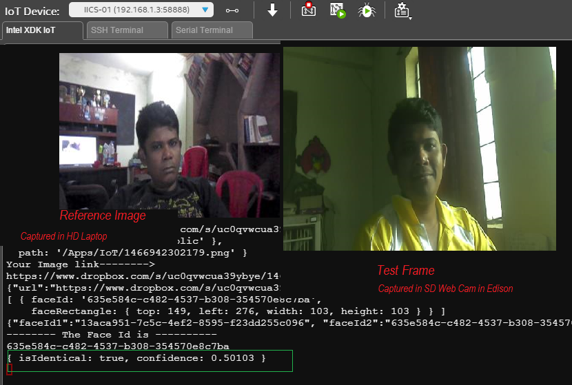
Figure 6.14 : Light, Pose and Camera independent face recognition of Microsoft Cognitive Face API
The test frame was captured during one of the live testing of the locker that we had built. You can clearly see the quality of the face recognition system here. Also, the latency (i,e. response time of the algorithm) of Microsoft's face API was found to be least among some of the services I tested. Many services failed this camera independent feature. So we will prefer Microsoft's Cognitive Service over the others.
Go to face API explorer home page
You can put a photo of yours in Dropbox and test the detection service right at the home page.
Important: Dropbox links have dl=0 extension which means that APIs can't process them. So, be it knurld or Face API, you need to change the dropbox url from dl=0 to dl=1. [We will handle this in code!!]
Here is an analysis by Face API of a photo of me with my beloved wife.

Figure 6.15 : Face Detection Service of Microsoft's Face API
The API returns a JSON object which is easy to parse.
2 faces detected

JSON:
[
  {
    "faceId": "d4dfe717-796c-43d7-985f-21f2c9ac9fca",
    "faceRectangle": {
      "width": 189,
      "height": 189,
      "left": 356,
      "top": 174
    },


    },
    "faceAttributes": {
      "age": 33.5,
      "gender": "female",
      "headPose": {
        "roll": 3.1,
        "yaw": -16.8,
        "pitch": 0
      },
      "smile": 0.975,
      "facialHair": {
        "moustache": 0,
        "beard": 0,
        "sideburns": 0
      },
      "glasses": "NoGlasses"
    }
  },
  {
    "faceId": "89477e90-cbbc-4aac-b9fc-6340d365e6ed",
    "faceRectangle": {
      "width": 176,
      "height": 176,
      "left": 207,
      "top": 138
    },
    "faceLandmarks": {

      }
    },
    "faceAttributes": {
      "age": 39,
      "gender": "male",
      "headPose": {
        "roll": 15.3,
        "yaw": -6.7,
        "pitch": 0
      },
      "smile": 1,
      "facialHair": {
        "moustache": 0,
        "beard": 0,
        "sideburns": 0
      },
      "glasses": "NoGlasses"
    }
  }
]
I have removed facelandmarks attribute which presents start and end of each of the landmark points in the face.
So, the service offers multi face detection with attribute for each faces. Gender, Smile analysis and Head posture can be used in conjunction with face recognition for better recognition service. For instance, you can use Smile and Posture to implement a liveness detection by the application program. You can randomly ask the user "tilt your face on left side and smile". If the analysis returns a left posture ( from roll, pitch yaw) The user is responding to the program dynamically and is considered to be live subject.
This project however, doesn't implement a liveness detection with faces as voice does that for us.
Interestingly you can see that every face that you analyze with Face APIs is given an unique ID. faceId of Face presented during enrollment ( which is handled logically by our program) and the faceID generated by analyzing test face during verification can be supplied to faceVerification API to get the matching result.
The coolest thing about MCS Face API is that, you can test both of our test cases without creating any account and without any hassle.
In the same home page you can test the verification process also!
Once confident of the roboustness of the algorithm, simply create a free account. You can explore all the services from OxfordAI's API testing Console
In our case we will use only two APIs: Face Detection and Face Verification. Enrollment will be handled logically. When you submit a face during "enrollment" in PC App, it will return a face ID. We will save this ID in a file and will be sent to Edison via MqTT. Edison will save this ID in a file.
When user photo is taken during verification, Edison will first submit that for detection. A new ID will be sent back. This verification faceID and stored registration time faceID will be sent to verification service which will return a similary measure. Based on sensitivity of your application, you can set a threshold for accepting or rejecting the verification photo.
So, create your account and test the APIs from the console. That would give you a world of confidence before you go for implementation.
As, both Knurld as well as MCS needs remote URL, we will use Dropbox as a bridge and as storage as service to store our audio and photo and pass them to respective end points. In next section we will quickly walk you through the Dropbox APIs needed for this project.
6.5 Dropbox - The bridge between App and Biometric Endpoints
Most of you I assume already have a Dropbox account . If you do not have one, create. It is a cool Cloud storage service provider.
Now, we are interested in accessing some of the Dropbox APIs. So go to Dropbox developers, click on oAuth follwed by token/revoke.
Click on 'Get Token' to get the token. You will see the access token as seen in figure 6.16.

Figure 6.16 Fetching Dropbox Access token
This is all you need to develop an application.
We are interested in accessing two apis: upload and get shared links.
For uploading we will use libraries in c# in PC app and Node.js for device app. While uploading, you need to specify your folder. / refers to as the root folder. /Photos refers to as the Photos folder in your dropbox.
Whatever folder you specify while uploading, the same needs to be passed for getting the shared link.
curl -X POST https://content.dropboxapi.com/2/sharing/get_shared_link_file \ --header 'Authorization: Bearer <My access token>' \ --header 'Dropbox-API-Arg: {"url":""}'
This API call through a HTTP Client in your program will return a remote URL for the specific file. From your program you need to change trailing dl=0 with dl=1 and pass that to respective endpoints while working with face recognition and voice recognition.
Well, that is pretty much background information you need to create Biometric locker. You are now ready to do what you in codeproject do best, i.e. code.
But before we jump into our most favourite part of the tutorial let us recall what we learnt in this chapter once.
Chapter Summery
- Knurld API structure, process and working.
- How to test the APIs.
- Microsoft's Face API structure and Calls
- Dropbox APIs.
- You created a Dropbox developer account, Knurld developer account and subscribed to Microsoft's Cognitive service's face API. You obtained an access token from your MCS API console.
- We learnt about some fundamentals of face and voice recognition and why multi modal biometric is more secured.
- We developed a general understanding of API testing and learnt how the API end points can be called in a platform independent ways.
Finally, after hours of learning, account creation, API testing, fabrication, time has come to put them all into a single, Integrated IoT application. Let us go to coding section, which I am sure will be the easiest part of this article for you to follow!
7. Coding-Developing Software Suite for the Locker
You already know that our overall software suite will have two distinct apps running in two different machines ( and devices).
The PC app does following operations:
- User account creation with Knurld
- User's Voice Enrollment.
- User's Face Enrollment
- Establishes a MqTT bridge with Edison device. Speaks out the messages coming from devices using Text2Speech.
- Send Consumer ID after Voice Enrollment to Device App
- Send faceID acquired during face registration to device app
The device app on the other hand will be developed in Intel XDK with Node.js. it will have to perform following operations:
- It should be able to exchange MqTT messages with PC APP
- Store faceID and ConsumerID in files
- Wait for user to press a button
- When user press the locker button, if the state is "Open Locker", initialize face verification process
- If face is successfully verified, initiate voice verification.
- If voice verification is successful, go for locker open by controlling servo motor
You can refer to reference sequence diagram once more to have another closer look at the detailed process flow sequence.
With these points in mind, let us move towards our PC app and design and develop that.
7.1 Pc App

The PC App will be developed in Windows Form application. You are welcomed to design a WPF version for it. The Settings app must keep scanning for the device and get connected with the device when it is available. Our device app periodically sends "Hello" MqTT Message. So this app subscribes to MqTT channel. When it receives the Hello message, it gives a message that 'connected to device'.
7.1.1 Setting And Registration
We use M2MQTT Client library for publish and scbscribe of MqTT. Download the Dll and add as a reference to the project. It needs .net framework 4.0 and above. So, your project target has to be >4.0.
 BackgroundWorker bwStart = new BackgroundWorker();
public static MqttClient mc = null;
        public static string topic = "rupam/Locker";
        string broker = "iot.eclipse.org";
        System.Speech.Synthesis.SpeechSynthesizer speaker = new System.Speech.Synthesis.SpeechSynthesizer();
We declare a MqTT Client called mc. We define a channel "rupam/Locker" for message exchange.
We declare a BackgroundWorker bwStart to initiate the connection with iot.eclipse.org in the background.
The worker is run in the Form_Load() event
 bwStart.DoWork += bwStart_DoWork;
            bwStart.RunWorkerCompleted += bwStart_RunWorkerCompleted;
            bwStart.WorkerSupportsCancellation = true;
            bwStart.RunWorkerAsync();
In DoWork, we initialize connection to broker.
void bwStart_DoWork(object sender, DoWorkEventArgs e)
        {
            mc = new MqttClient(broker);

            mc.Connect("RUPAM");
            //throw new NotImplementedException();
        }
In the RunWorkerCompleted() we subscribe to MqTT message.
 void bwStart_RunWorkerCompleted(object sender, RunWorkerCompletedEventArgs e)
        {

            mc.Subscribe(new string[] { topic }, new byte[] { (byte)0 });
            mc.MqttMsgPublishReceived += mc_MqttMsgPublishReceived;
            tssLabel.Text = "Connected to IoT Hub";

        }
You can observe that we subscribe to the topic before adding message received event handler. mc_MqttMsgPublishedReceived is the bridge between device and pc app. Message is received as binary message which is converted to text first.
void mc_MqttMsgPublishReceived(object sender, uPLibrary.Networking.M2Mqtt.Messages.MqttMsgPublishEventArgs e)
        {
            this.Invoke((MethodInvoker)delegate
            {
                if (e.Message[1] == (byte)0)
                {
                    //  listBox1.Items.Add(GetString(e.Message));

                }
                else
                {
                    try
                    {
                        string command = "";
                        for (int i = 0; i < e.Message.Length; i++)
                        {
                            //  command = command + ('A' + ((int)e.Message[i] - 64));
                            command = command + ((char)('A' + ((int)e.Message[i] - 65))).ToString();

                        }
                        //MessageBox.Show(command);

                        if (command.Contains("Connected")  )
                        {
                            if (labConnection.Text.Contains("Not"))
                            {
                                labConnection.Text = "Locker Connected";
                                speaker.Rate = -1;
                                speaker.Speak(command);
                                mc.Publish(topic,GetBytesForEdison("Connected to App"));
                            }
                        }
                        else
                        {
                            speaker.Rate = -1;
                            speaker.Speak(command);
                        }
                    }
                    catch
                    {
                    }
                }
            });
        }
Initially labConnection text is set to "not connected". From device we periodically send a MqTT mesasge called "Connected Cashbox". This function checks for the word 'Connected'. When it receives the message, it checks whether the device is already connected or not, if not then it changes labConnection's text and triggers a speech.
If we do not use this and trigger a speech upon reception of every "Hello" message, in every 2-5 seconds the Setting App will speak out "Connected". We convert the binary message to ASCII by subtracting 65 from the number and adding it to char 'A'.
If the command doesn't contain the word 'Connected" then it is a log message from the device, so, irrespective of the content we speak it out in the else part.
Clicking on Account Settings button brings up second form which is frmPassword. The runtime of the form is as shown in figure 7.2.

Figure 7.2 Runtime of frmPassword of PC App
The form checks if the user is registered or not by checking for a file entry in /AppData/Roaming/IntegratedIdeas/IoTBiometric/consumer.txt. If it doesn't exist, it tells the user that he needs to register. At the same time the app detects the PC user name and puts that into user name field for simplifying the registration further.
This form also has two pictureboxs: The larger one renders frames acquired by camera and smaller one renders the segmented face. The frame rendering and segmentation part is adopted from Sergio's Multi face recognitoon tutorial that we had referred in face recognition section. We use EmguCV for frame capture and local face detection.
Face detection is provided with the form so that user knows that the face detection is working locally before going for registration.
In the Form_Load method we initialize camera and add an event handler to Application.Idle called FrameGrabber for capturing frames from camera.
    #region initialize face

            try
            {
                face = new HaarCascade("haarcascade_frontalface_default.xml");

                grabber = new Capture(0);
                grabber.QueryFrame();

                //Initialize the FrameGraber event
                Application.Idle += new EventHandler(FrameGrabber);
            }
            catch
            {
                MessageBox.Show("can not start camera","Error",MessageBoxButtons.OK,MessageBoxIcon.Error);
            }
            #endregion
Where face and grabber are declared as bellow
 #region face related declarations
        Image<Bgr, Byte> currentFrame;
        public Capture grabber;
        HaarCascade face;

#endregion
In FrameGrabber method, we detect face, segment it and display it in small face thumbnail box.
     void FrameGrabber(object sender, EventArgs e)
        {

            currentFrame = grabber.QueryFrame().Resize(320, 240, Emgu.CV.CvEnum.INTER.CV_INTER_CUBIC);
           picMain.BackgroundImage = new System.Drawing.Bitmap(currentFrame.Bitmap, picMain.Size);
           gray = currentFrame.Convert<Gray, Byte>();

                    //Face Detector
                    MCvAvgComp[][] facesDetected = gray.DetectHaarCascade(
                  face,
                  1.2,
                  10,
                  Emgu.CV.CvEnum.HAAR_DETECTION_TYPE.DO_CANNY_PRUNING,
                  new System.Drawing.Size(20, 20));

                    //Action for each element detected
                    foreach (MCvAvgComp f in facesDetected[0])
                    {
                        t = t + 1;
                       var imFace = currentFrame.Copy(f.rect).Resize(picFace.Width, picFace.Height, Emgu.CV.CvEnum.INTER.CV_INTER_CUBIC);
                       picFace.Image = imFace.Bitmap;
                    }
            // Calling FaceSdk.


        }
This method is "inspired by" Sergio's project in Sillicon Valley term, but in normal English, it is called a "shameless lift" from that project :)
If the user account is not registered, clicking on Register button triggers user registration with Knurld. As HttpCalls are all blocking, we want them to be performed as a background process. We need to tell the backgroundWorker associated with Knurld call as which operation should be called. We do that with an enum called KnurldOperations.
public enum KnurldOperations { AUTHORIZE, REGISTER, CHANGE_PASSWORD, INIT_ENROLLMENT, SUBMIT_ANALYSIS, ENROLL, INIT_RECOGNITION, RECOGNIZE, AUTHENTICATE,NONE,INIT_VERIFICATION, ENROLLMENT_INSTRUCTIONS,DROPBOX_UPLOAD, DROPBOX_SHARE,GET_ANALYSIS,VERIFICATION_INSTRUCTIONS,VERIFY,VERIFICATION_STATUS};
So, during registration, we set the Operation type to REGISTER and call RunWorkerAsyn() for bw.
 if (btnOK.Text.Equals("Register"))
            {
                timHttpProgress.Enabled = true;
                toolStripProgressBar1.Value = 0;
                Operation = KnurldOperations.REGISTER;
                bw.RunWorkerAsync();
                tssMessage.Text = "Registration in Progress";
            }
I have created a well documented class called KnurldHelper for abstracting calls to Knurld's APIs.
Let's first have a look at the RegisterUser method of our KnurldHelper class before going to DoWork of bw.
 #region Registration and User/consumer related Apis
        /// <summary>
        /// This method registers a user and return the user specific URL called Consumer.
        /// There is no validation at the server side. So you must handle the validation in your code
        /// For instance check for blank username or password and so on.
        /// </summary>
        /// <param name="username">Unique username</param>
        /// <param name="password">password of any length/format/alpha numeric</param>
        /// <param name="gender">Gender M or F</param>
        /// <returns>consumer if registration is successfull else return error</returns>
       public static string RegisterUser(string username, string password,string gender)
       {
           try
           {
               var request = (HttpWebRequest)WebRequest.Create("https://api.knurld.io/v1/consumers");

               request.Headers.Add("Authorization", "Bearer " + AccessToken);
               request.Headers.Add("Developer-Id", "Bearer: " + DeveloperId);

               request.Method = "POST";
               request.ContentType = "application/json";

               // adding paremeters

               string s = "{\"username\":\"" + username + "\",\"gender\":\"" + gender + "\",\"password\":\"" + password + "\"}";

               var postData = s;
               var data = Encoding.ASCII.GetBytes(postData);
               using (var stream = request.GetRequestStream())
               {
                   stream.Write(data, 0, data.Length);
               }

               dynamic response = (HttpWebResponse)request.GetResponse();

               var responseString = new StreamReader(response.GetResponseStream()).ReadToEnd();
               dynamic result = JObject.Parse(responseString);
               var consumer = result["href"].ToString();
               return consumer;
           }
           catch (WebException we)
           {
               string responseError = new StreamReader(we.Response.GetResponseStream()).ReadToEnd();
               dynamic result = JObject.Parse(responseError);
               string s = "";
               if (result.ToString().Contains("fault"))
               {
                   s = "Error :-" + result["fault"]["faultstring"] + "\n" + result["fault"]["detail"]["errorcode"].ToString();
               }
               else if (result.ToString().Contains("message"))
               {
                   s = s + "Error :- " + result["message"];
               }
               else
               {
                   s = result["ErrorCode"] + "\n" + result["Error"];
               }
               return s;

           }
       }
Compare the implementation of this method with Knurld's API endpoint.
We create a HttpWebRequest object and call the API end point. We put AccessToke, which is acquired by calling FetchAccessToken() when the frmMain is loaded. The method is listed below. The access token and the DeveloperID, which needs to be provided by user are supplied as header parameters for the request. We form a JSON compatible string for Payload where username, gender and password fields are supplied. This string s or postData is converted into byte format which is sent as the payload of the request by calling Encoding.ASCII.GetBytes(postData)
Note that HttpWebRequest is present in System.Web dll which is not availabnle for Client Profile framework. So while selecting a .Net frameowrk, please do not select 4.0 Client profile.
Remember, that when consumer is created it returns a complete url in href filed of the response. So we parse the response and return this as result.
We also handle WebException. The API end point returns a "fault string" message if the payload is not in proper JSON format. For every other cases, it returns a JSON error string containing HTTP error as well as error Description. We want our method invoker to distinguish between a valid response and error. So we append a simple "Error:-" string with the error message before returning it. The calling part, (RunWorkerCompleted) upon getting a response will check "Error:-" in the return string. If it finds that string chunk then suitable error message will be displayed to the user.
Let's have a look at our FetchAccessToken() method. Remember we had discussed about calling this method from Knurld's API explorer in Knurld API section previously. Compare the curl request in that section with the implementation below.
#region Authorization
        /// <summary>
        /// This method is called first to set the access token to the app
        /// This automatically takes ClientId and ClientSecret from the publice class members
        /// </summary>

        public static string FetchAccessToken()
        {
            try
            {
                var request = (HttpWebRequest)WebRequest.Create("https://api.knurld.io/oauth/client_credential/accesstoken?grant_type=client_credentials");

                var postData = "client_id="+ClientId;//94CtiIKAyjhZAvJhT4X6RJIOxXY80hAw
                postData += "&client_secret="+ClientSecret;
                var data = Encoding.ASCII.GetBytes(postData);

                request.Method = "POST";
                request.ContentType = "application/x-www-form-urlencoded";
                request.ContentLength = data.Length;

                using (var stream = request.GetRequestStream())
                {
                    stream.Write(data, 0, data.Length);
                }

                dynamic response = (HttpWebResponse)request.GetResponse();

                var responseString = new StreamReader(response.GetResponseStream()).ReadToEnd();
                dynamic result = JObject.Parse(responseString);
                AccessToken = result["access_token"];
                return AccessToken;
            }
            catch (WebException we)
            {
                string s = DecodeException(we);
                return s;

            }
        }
        #endregion
DecodeException() is a method which simply implements the WebException handling part of RegisterUser method so that for every API call, in WebException handling part, you can simply call this method to parse your exception into a String.
We change request.Method to "POST" or "GET" based on Knurld API end point documentation. Because every end point call will retrun a different JSON string, we capture the response into a dynamic data type called response. Then based on API reference, we parse and extract our field of interest.
KnurldHelper is initialized by calling InitAll() method.
/// <summary>
        /// This method MUST BE CALLED prior to using any other methods of this class. This sets up the sdk
        /// </summary>
        /// <param name="ClientId">Your ClientID</param>
        /// <param name="ClientSecret">Your Client Secret</param>
        /// <param name="DeveloperId">Without "Bearer:" keyword</param>
        /// <param name="Company">Company name</param>
        /// <param name="Product">App name. This sdk creates a directory: \Users\Username\AppData\Roaming\CompanyName\ProductName and puts all resources there</param>
        public static void InitAll(string ClientId,string ClientSecret,string DeveloperId,string Company, string Product)
        {
            KnurldHelper.ClientId = ClientId;
            KnurldHelper.ClientSecret = ClientSecret;
            KnurldHelper.DeveloperId = DeveloperId;
            KnurldHelper.CompanyName = Company;
            KnurldHelper.ProductName = Product;
            Path = Environment.GetFolderPath(Environment.SpecialFolder.ApplicationData) + "\\" + CompanyName + "\\" + ProductName + "\\";
        }
Observe that this method requires the user to provide company name and application name as parameters. We create a directory in C:\Users\<user>\AppData\Roaming\Company\App folder and keep all our text files like one containing consumer URL, AppID there.
For obtaining these files, the helper's Path property needs to be used which abstracts the storage directory from the user. Because InitAll() initializes all the fields needed by path, your program doesn't have to worry about creating and managing application directory for the project.
public static string Path
        {
            set
            {
               path = value;
               if (!Directory.Exists(path))
               {
                   Directory.CreateDirectory(path);
               }
            }
            get
            {
                path = Environment.GetFolderPath(Environment.SpecialFolder.ApplicationData) + "\\" + CompanyName + "\\" + ProductName + "\\";

                return path;
            }
        }
Having understood how the KnurldHelper methods work, let us go back to calling part. Recall that we are calling these methods from bw_DoWork() method depending upon the value of KnurlOperation type variable Operation which is set by our GUI before calling bw.RunWorkerAsync(). Let's see the DoWork method.
void bw_DoWork(object sender, DoWorkEventArgs e)
        {


            switch (Operation)
            {
                case KnurldOperations.REGISTER:
                    string gender="M";
                    if(radioButton2.Checked)
                    {
                        gender="F";
                    }
                    result = Knurld.KnurldHelper.RegisterUser(txtUname.Text, txtNewPwd.Text, gender);
                    break;
                case KnurldOperations.AUTHENTICATE:
                    result = Knurld.KnurldHelper.Authenticate(txtUname.Text, txtOldPwd.Text);

                    break;
                case KnurldOperations.CHANGE_PASSWORD:
                    result = Knurld.KnurldHelper.ChangePassword(File.ReadAllText(frmMain.Path + "consumer.txt"), txtNewPwd.Text);
                    break;
            }
            //throw new NotImplementedException();
        }
When we obtain the result ( which is either exception or a valid http response) we might need to access GUI components depending upon the result. Hence, result String is declared globally. Once result is obtained, RunWorkerCompleted() part is called where we implement the decison logic.
Let's see the REGISTER part of the RunWorkerCompleted() method
switch (Operation)
            {

case KnurldOperations.REGISTER:
                    toolStripProgressBar1.Value = 0;
                    timHttpProgress.Enabled = false;
                    if (result.Contains("Error"))
                    {
                        MessageBox.Show(result, "Registration Error", MessageBoxButtons.OK, MessageBoxIcon.Error);
                        txtUname.Focus();
                        tssMessage.Text = "Registration Failed";
                    }
                    else
                    {
                        MessageBox.Show(txtUname.Text+" is registered", "Registration Suuccessful", MessageBoxButtons.OK, MessageBoxIcon.Information);
                        File.WriteAllText(frmMain.Path + "Consumer.txt", result);
                        File.WriteAllText(frmMain.Path + "User.txt", txtUname.Text);
                        tssMessage.Text = txtUname.Text + " is registered now";
                        grpVoice.Visible = true;
                    }
                    break;

//...... other cases here...... We are only checking Register method.

}
You can clearly see that we have separated Error handling logic from HTTP 200 cases. The else part of the above code is the valid response. When consumer url is returned by RegisterUser() method, the url is written in the specific path.
You may ask a simple question here. Why not use Async? Well, I am not to comfortable with Async methods and don't have efficiency in writing them. You are free to import these methods into Async based style.
You may also ask why a file database? Can we use SQLLite? You certainly can. As We don't need to store too many data here( remember our data is at the cloud) and as I had to deal with dumping a lot of raw responses in Log while developing the code, I preferred a file database where I could dump the response, open with a text editor, analyze and develop the code alongside.
Once the registration is successful, Enroll Voice Button in frmPassword becomes visible. See the result of registration in figure 7.3

Figure 7.3 : Result of User John's registration
In case if you are wondering why John( or who is John) and why not Rupam, I have already created several variations of Rupam and have no patience of changing the name after "User already exists" message. So John( a random name that came to my mind!!!)
After registration, the app tests for enrollment.txt in Application path which is not found as voice is not enrolled. So it shoots up a message and keeps the button active. Clicking in this button
7.1.2 Voice Registration(Enrollment)
Voice registration needs to perform following tasks:
- Init verification by passing AppModel,
- Parse the response and extract instructions
- Speak out the instructions to user
- Record User's voice
- Save the recorded audio
- Upload the audio to dropbox
- get Dropbox link
- change dl=0 to dl=1 in the url
- Submit the audio for analysis
- once the JSON analysis araay of start and end intervals is obtained, fetch it and append the phrases
- Send this to Enroll function
- Keep polling GetEnrollment status till the Api end point returns initialized.
- Once the status is success, return the consumer URL to our device.
- Also, as the enrollment and verification both depends upon the audio recording quality, we need to ensure that the audio quality is just right for the recording.
As there are many steps and it takes about 15-30s for voice enrollment ( beside recording) we provide all the information about individual Labels in the frmVoice form and keep changing the text of these labels with a tick symbol as the processes get completed one after the other.
Let's take a look at our frmVoice form in figure 7.4

Figure 7.4 : frmVoice in Run time
The moment frmVoice is loaded, accessToken is fetched once more as the lifespan of the Knurld acceToken is extremely small. We do not want the accessToken to be expired before our application is completed. Once access token is obtained, Enrollment is initialized. We obtain a url and set of instructions wheich are displayed at the top.
Recall that for Enrollment to work, the program needs to pass AppModel in the JSON data field. Recall that we created an AppModel through API Explorer in Knurld API section
In the Form_Load() method, we fetch the AppModel stored in App.txt in Path. If the App.txt is not in the path, it is copied from the current directory( as I am keeping the debug mode to Debug, it would be copied from Debug\App.txt to Path\App.txt. So, if you want to change the AppModel with the one you created, copy the text and replace the contents of App.txt in your Debug folder.
            Operation = KnurldOperations.INIT_ENROLLMENT;
            try
            {
                KnurldHelper.App = File.ReadAllText(frmMain.Path + "App.txt");
            }
            catch
            {
                File.Copy(".\\App.txt", frmMain.Path + "App.txt");
                KnurldHelper.App = File.ReadAllText(frmMain.Path + "App.txt");
            }
// Start the background process...

            bw = new BackgroundWorker();
            bw.DoWork += bw_DoWork;
            bw.WorkerReportsProgress = true;
            bw.WorkerSupportsCancellation = true;
            timer1.Enabled = true;
            bw.RunWorkerCompleted += bw_RunWorkerCompleted;
            bw.RunWorkerAsync();
Also, immidiately after fetching the AppModel, we initiate the background process. As the Operation is set to INIT_ENROLLMENT, it will call StartEnrollment() of KnurldHelper class.
 void bw_DoWork(object sender, DoWorkEventArgs e)
        {
            switch (Operation)
            {
                case KnurldOperations.INIT_ENROLLMENT:
                    result = Knurld.KnurldHelper.StartEnrollment(File.ReadAllText(frmMain.Path + "Consumer.txt"));
                    break;

// other cases will be discussed later
            }

     }
Note, the StartEnrollment() method needs consumerID (or url) as a parameter because it has to call /v1/enrollments/consumerID as the end point. The consumer url or consumerID was saved in Consumer.txt in Path after user registration was successful.
Let us have a look at the StartEnrollment() method, understanding which wouldn't be difficult now.
  #region Enrollment related APIs
        /// <summary>
        /// Starts a Voice Enrollment process for a registered user
        ///
        /// <param name="userHref">The url of the username.
        /// 1. Call GetAllConsumers(). var cons=GetAllConsumers()
        /// 2. the method gets App Id from Property Knurld.App. Make sure it is set by calling LoadMyApp()
        /// 3. Fetch url of the user. var url=ConsumerUrlFromUsername(cons,userName);
        /// 4. var enrollmentUrl=StartEnrollment(url);
        /// </param>
        /// /// <returns>Enrollment URL, required for a) Processing Audio=> Submitting Audio, Enroll</returns>
       /// </summary>
       public static string StartEnrollment(string userHref)
       {
           try
           {
               var request = (HttpWebRequest)WebRequest.Create("https://api.knurld.io/v1/enrollments");

               request.Headers.Add("Authorization", "Bearer " + AccessToken);
               request.Headers.Add("Developer-Id", "Bearer: " + DeveloperId);

               request.Method = "POST";
               request.ContentType = "application/json";

               // adding paremeters

               string s = "{\"consumer\":\"" + userHref + "\",\"application\":\"" + App + "\"}";

               var postData = s;
               var data = Encoding.ASCII.GetBytes(postData);
               using (var stream = request.GetRequestStream())
               {
                   stream.Write(data, 0, data.Length);
               }

               dynamic response = (HttpWebResponse)request.GetResponse();

               var responseString = new StreamReader(response.GetResponseStream()).ReadToEnd();
               dynamic result = JObject.Parse(responseString);
               string enrollmentJob = result["href"].ToString();
               return enrollmentJob;
           }
           catch(WebException we)
           {
               string s = DecodeException(we);
               return s;
           }
       }
As You can see, that we are sending userHref or the consumer ID and AppModel as request parameter and getting a response which contains an ID to current enrollment process called enrollmentJob. This job is needed while submitting Job order which should include result of Analysis. Analysis needs an audio file which user has to record following the instructions.
For recording Audio, we have created a class called SoundRecorder.cs which uses native windows method for Audio recording.
You can use this class in any windows form or wpf app for Audio recording.
namespace Knurld
{
   public class MySoundRecorder
    {
        [DllImport("winmm.dll")]
        private static extern int mciSendString(string MciComando, string MciRetorno, int MciRetornoLeng, int CallBack);
        public static bool isPaused = false;
        string musica = "";

        public static void Start()
        {
            mciSendString("open new type waveaudio alias Som", null, 0, 0);
            var WaveBitsPerSample = 16;
            var WaveChannels = 2;
            var WaveSamplesPerSec = 44000;
            var WaveBytesPerSec = WaveBitsPerSample * WaveChannels * WaveSamplesPerSec / 8;

            var WaveAlignment = WaveBitsPerSample * WaveChannels / 8;
            string command = "set Som time format ms";
            command += " bitspersample " + WaveBitsPerSample;
            command += " channels " + WaveChannels;
            command += " samplespersec " + WaveSamplesPerSec;
            command += " bytespersec " + WaveBytesPerSec;
            command += " alignment " + WaveAlignment;

            mciSendString(command, null, 0, 0);

            mciSendString("record Som", null, 0, 0);

        }
        public static void Pause()
        {
            mciSendString("pause Som", null, 0, 0);
        }
        public static void UnPause()
        {
            mciSendString("record Som", null, 0, 0);
        }
        public static void StopAndSave(string fname)
        {
            mciSendString("pause Som", null, 0, 0);


            if (File.Exists(fname))
            {
                File.Delete(fname);
                System.Threading.Thread.Sleep(200);
            }
            mciSendString("save Som " + fname, null, 0, 0);
            mciSendString("close Som", null, 0, 0);
        }

    }
}
Onserve we set a sampling rate of 44kHz, because our arecord of Device records audio only at 44kHz( cd quality). We want the registration and verification audio format to be same.
SoundRecorder.Start() and SoundRecorder.Stop("c:\users\Rupam\AppData\Roaming\IntegratedIdeas\IoTBiometric\abc.wav") are the calls corresponding to recording start and stop.
Observe that we are recording the audio inside our path.
One problem is that, we do not know what are the recording properties such as volume or current gain in db. Unfortunately the native SoundRecorder class doesn't send any response to UI. So in UI you get no hints about any signal change.
We create a simple hack to display variations in audio level as you record.
We take an object of Microsoft SpeechRecognizer, set it to dictation mode and then we acquire the signal level from it's event handler
private System.Speech.Recognition.SpeechRecognitionEngine speech = new System.Speech.Recognition.SpeechRecognitionEngine();
And in the Form_Load() method we initialize it as below
 // -- Set the speech synthesizer to use the default audio input device
            speech.SetInputToDefaultAudioDevice();
            // -- Tell the speech synthesizer to recognize plain speech, not commands.
            speech.LoadGrammar(new System.Speech.Recognition.DictationGrammar());
            // -- Start recognizing
            speech.RecognizeAsync(System.Speech.Recognition.RecognizeMode.Multiple);
By setting the RecognizeMode.Multiple we ensure that the speech object is continuesly listening to Audio.
As all the phrases are distinct English words, as you speak them, they will be recognized. We have nothing to do with the recognized words, but we get the audio level from as you speak in AudioLevelUpdated event handler.
private void speech_AudioLevelUpdated(object sender, System.Speech.Recognition.AudioLevelUpdatedEventArgs e)
        {
            try
            {
                pgAudioLevel.Value = e.AudioLevel;

            }
            catch
            {
            }

            //throw new NotImplementedException();
        }
One of the Problems with Knurld and Even Microsoft's APIs is that if you submit the same URL for verification or registration the end points rejects them.
Which means that even if I have recorded an entire new audio in an existing file name ( eg: my.wav) and have uploaded it in dropbox afresh, when you share that link with the API end point, it will genrate an error. It simply means that every filename ( for both audio as well as for image) needs to be unique.
So, when user clicks on "Stop" button after speech is recorded, we generate a new file based on current date and time and save it inside Path. We then set the Operation to DROPBOX_UPLOAD which initiates the dropbox file upload method.
if (Mode.Equals("Enrollment"))
            {
                string n = string.Format("{0:yyyy_MM_dd_hh_mm_ss_tt}", DateTime.Now);
                audioFileName = user + "_" + n + "_"+count+"enrollment.wav";
                count++;
                MySoundRecorder.StopAndSave(frmMain.Path + audioFileName);
                tssMessage.Text = "Audio Saved. Uploading to DropBox";
                Operation = KnurldOperations.DROPBOX_UPLOAD;
                toolStripProgressBar1.Value = 0;
                timer1.Enabled = true;
                bw.RunWorkerAsync();
            }
For uploading file to Dropbox we use Nemiro.oAuth class library which makes uploading an extremely easy affair.
   case KnurldOperations.DROPBOX_UPLOAD:
                    OAuthUtility.PutAsync
    (
      "https://api-content.dropbox.com/1/files_put/auto/",
      new HttpParameterCollection
        {
          {"access_token", dropboxAccessToken},
          {"path","/"},
          {"overwrite", "true"},
          {"autorename","true"},
          {File.OpenRead(frmMain.Path+audioFileName)}
        },
      callback: Upload_Result
    );
                    break;
"/" in path means the audio will be saved to your Dropbox's root directory.
In the Upload_Result callback, we check for HTTP status of the call. If the status is 200, it means that the file is successfully uploaded. once it is uploaded, we call AudioSharePath() method to share the link of just uploaded file.
private void Upload_Result(RequestResult result)
        {
            if (this.InvokeRequired)
            {
                this.Invoke(new Action<RequestResult>(Upload_Result), result);
                return;
            }

            if (result.StatusCode == 200)
            {
                tssMessage.Text="File Uploaded. Getting Link";

                AudioSharepath(audioFileName);
            }
            else
            {
                if (result["error"].HasValue)
                {
                    MessageBox.Show(result["error"].ToString(), "Error", MessageBoxButtons.OK, MessageBoxIcon.Error);
                }
                else
                {
                    MessageBox.Show(result.ToString(), "Error", MessageBoxButtons.OK, MessageBoxIcon.Error);
                }
            }
        }
AudioSharePath() must share a link of the file, obtain the link change the trailing dl=0 to dl=1 we we have discussed early and start the Analysis process. Recall that Analysis end point has to analyze the given audio and return a JSON object containing the array of start and end interval of the phrases.
   public void AudioSharepath(string fname)
        {
            try
            {
                var request = (HttpWebRequest)WebRequest.Create("https://api.dropboxapi.com/2/sharing/create_shared_link");

                request.Headers.Add("Authorization", "Bearer " + dropboxAccessToken);

                request.Method = "POST";
                request.ContentType = "application/json";

                string s = "{\"path\":\"" + "/" + fname + "\"}";

                var postData = s;
                var data = Encoding.ASCII.GetBytes(postData);
                using (var stream = request.GetRequestStream())
                {
                    stream.Write(data, 0, data.Length);
                }

                dynamic response = (HttpWebResponse)request.GetResponse();

                var responseString = new StreamReader(response.GetResponseStream()).ReadToEnd();
                dynamic result = JObject.Parse(responseString);
                string url = result["url"].ToString().Replace("dl=0", "dl=1");
                labCloud.Text = "\u221A Cloud Storage";
                dropboxUrl = url;
                //// Once File is Uploaded, submit the url for Analysis///////////////
                tssMessage.Text = url;
                File.Delete(fname);
                toolStripProgressBar1.Value = 0;
                timer1.Enabled = true;
                tssMessage.Text = "Starting Analysis";
                Operation = KnurldOperations.SUBMIT_ANALYSIS;
                bw.RunWorkerAsync();
                /////////////////////////////////////////////////////////////


            }

            catch (WebException we)
            {
              string s= KnurldHelper.DecodeException(we);
              MessageBox.Show(s, "Analysis Error", MessageBoxButtons.OK, MessageBoxIcon.Error);
            }
        }
We call SubmitAudioForAnalysis from bw.DoWork.
if (Mode.Equals("Enrollment"))
                    {
                        result = KnurldHelper.SubmitAudioFileUrlForAnalysis(dropboxUrl,9);
                    }
The Analysis end point needs wordCount as one of the request parameters.
Recall that for Enrollment, all the three phrases are to be repeated three times each. Hence we pass 9 as parameter. The method returns an analysisUrl which is in the field called taskName. It also returns a status with value "initialized". The program has to poll the GetAnalysisStatus end point till it returns a status value "completed" ( or a http error).
Let's see the handling of GET_ANALYSIS is RunWorkerCompleted() method where the result of analysis is available.
case KnurldOperations.GET_ANALYSIS:
                    bw.CancelAsync();
                    if(result.Equals("Processing"))
                    {
                    // Keep Polling the GetAnalysisStatus end point till the status is processing
                        System.Threading.Thread.Sleep(100);
                        timer1.Enabled = true;
                        Operation = KnurldOperations.GET_ANALYSIS;
                        bw.RunWorkerAsync();
                        return;
                    }
                    else if (result.Contains("Error"))
                    {
                        MessageBox.Show(result, "Analysis Error", MessageBoxButtons.OK, MessageBoxIcon.Error);
                        return;
                    }

                    intervals = result;

                    if (Mode.Equals("Enrollment"))
                    {
                        tssMessage.Text = "Analysis Successful. Enrolling";
                    }
                    else
                    {
                        tssMessage.Text = "Analysis Successful. Verifying";
                    }
                    labAudioAnalysis.Text = "\u221A AudioAnalyzed";
                    //MessageBox.Show(result);
                    toolStripProgressBar1.Value = 0;
                    timer1.Enabled = true;
                    if(Mode.Equals("Enrollment"))
                    Operation = KnurldOperations.ENROLL;
                    else
                        Operation = KnurldOperations.VERIFY;
                    bw.RunWorkerAsync();
                    break;
Once the status is completed, we assign the result in a local variable called intervals. Finally we set the Operation as ENROLL which calls KnurldHelper.Enroll() method
Enroll method appends the phrases fromvocabulary, each repeated three times and creates a payload. dropBoxUrl and this payload is submitted for Enrollment
public static string Enroll(string enrollmentJob,string intervals,List<string>vocab,string dropboxUrl)
       {
           try
           {
               // var responseString = HttpUploadEnrollmentFile(enrollmentJob, fname, "filename", "audio/wav", new NameValueCollection());

               var request = (HttpWebRequest)WebRequest.Create(enrollmentJob);

               request.Headers.Add("Authorization", "Bearer " + AccessToken);
               request.Headers.Add("Developer-Id", "Bearer: " + DeveloperId);

               request.Method = "POST";
               request.ContentType = "application/json";

               // adding paremeters
               //listBox1.Items[0].ToString(), listBox1.Items[1].ToString(), listBox1.Items[2].ToString()
               string s = "{\"enrollment.wav\":\"" + dropboxUrl + "\" ,\"intervals\":[";
               JArray interval = JArray.Parse(intervals);

               int n = 0;
               for (int i = 0; i < interval.Count - 1 && i < 8; i++)
               {

                   string s1 = "{\"phrase\":\"" + vocab[i / 3] + "\",\"start\":" + interval[i]["start"] + ",\"stop\":" + interval[i]["stop"] + "} ,";
                   s = s + s1;
                   n++;
               }
               int last = (n - 1) / 3;
               if (last >= 3)
               {
                   last = 2;
               }
               string s2 = "{\"phrase\":\"" + vocab[last] + "\",\"start\":" + interval[interval.Count - 1]["start"] + ",\"stop\":" + interval[interval.Count - 1]["stop"] + "}] }";
               s = s + s2;
               var postData = s;
               var data = Encoding.ASCII.GetBytes(postData);
               using (var stream = request.GetRequestStream())
               {
                   stream.Write(data, 0, data.Length);
               }

               dynamic response = (HttpWebResponse)request.GetResponse();

               var responseString = new StreamReader(response.GetResponseStream()).ReadToEnd();
               dynamic result = JObject.Parse(responseString);
               string enrollmentUrl = result["href"].ToString();
               return enrollmentUrl;

           }
           catch (WebException we)
           {
               string s = DecodeException(we);
               return s;
           }
           catch (IndexOutOfRangeException ie)
           {
               return "Error :- Phrases were not extracted properly in Audio.\nRecord Again";
           }
           catch (ArgumentOutOfRangeException aoe)
           {
               return "Error :- Not all the phrases were extracted. Please try again";
           }
       }
In the RunWorkerAsync() part which handles operation ENROLL, once the Enrollment is successful, we write the enrollment url in Path/enrollment.txt and send consumerUrl with a : delimited "consumerUrl" string over MqTT which when received by our device ( The locker) , is updated into the device storage. That url is used by the device for verification.
case KnurldOperations.ENROLL:

if (!result.Contains("Error"))
                    {
                        Operation = KnurldOperations.NONE;
                        timer1.Enabled = false;
                        toolStripProgressBar1.Value = 0;
                        string enrollmentStatus = result;
                        tssMessage.Text = "Enrolled";
                        labComplete.Text = "\u221A Completed";
                        File.WriteAllText(frmMain.Path + "enrollment.txt", enrollmentUrl);
                        MessageBox.Show("Enrollment Suucessful");
                        frmMain.mc.Publish(frmMain.topic,frmMain.GetBytesForEdison("consumerUrl#"+File.ReadAllText(frmMain.Path+"consumer.txt")));
                        btnDoneCancel.Text = "Done";
                        btnDoneCancel.Image = Image.FromFile("Ok.png");
                    }
                    else
                    {
                        MessageBox.Show(result, "Enrollment failed", MessageBoxButtons.OK, MessageBoxIcon.Error);
                    }
                    break;
That's the end of our frmVoice and the Enrollment process. You are advised to keep the CURL requests open while analyzing the code in the call. KnurldHelper is a wrapper of KnurldAPI calles. You can use that class with SoundRecorder and Dropbox methods to integrate VoiceRecognition service with any applications.
having registered user voice, let us now turn our focus to face APIs. Face APIs are relatively uncomplicated with only four overall calls: detection, photo upload, link sharing and verify. Verify is implemented at the device side. So you are literally using three API calls. Out of the three you have already developed methods for two dropbox calls. So, working with Face API in PC App is effectively getting faceID by calling faceDetection end point and passing that ID to our device.
Automatically adjusting the Recording volume
Even after implementing the rather complex process flow of Knurld APIs, you may encounter several problemes in both registration as well as in verification. Most of these problems arises from improper recording volume and gain level. Therefore in this project I have implemented a logic to automatically adjust the recording volume.
After several hours of trials and errors I have found out that 70% recording volume works best with Knurld services where gain must be 0 db. Setting the proper Audio level must never be left on end user. It is never a good idea from a user experience point of view. So we need some ways to hook to master volume service and adjust that from application program. Recall that we have already hacked Speechrecognization's AudioLevelUpdated() event handler for getting the current Audio level. All we need now is to hook the desired value with the master recording volume.
We use Naudio, a low level audio DSP helper to accomplish this.
#region Naudio
            try
            {
                //Instantiate an Enumerator to find audio devices
                NAudio.CoreAudioApi.MMDeviceEnumerator MMDE = new NAudio.CoreAudioApi.MMDeviceEnumerator();
                //Get all the devices, no matter what condition or status
                NAudio.CoreAudioApi.MMDeviceCollection DevCol = MMDE.EnumerateAudioEndPoints(NAudio.CoreAudioApi.DataFlow.All, NAudio.CoreAudioApi.DeviceState.All);
                //Loop through all devices
                foreach (NAudio.CoreAudioApi.MMDevice dev in DevCol)
                {
                    try
                    {

                        if (dev.DataFlow.Equals(NAudio.CoreAudioApi.DataFlow.Capture))
                        {
                            //Get its audio volume
                            System.Diagnostics.Debug.Print("Volume of " + dev.FriendlyName + " is " + dev.AudioEndpointVolume.MasterVolumeLevel.ToString());


                         Slider1.Value=(int)(dev.AudioEndpointVolume.MasterVolumeLevelScalar*100);

                        }
                    }
                    catch (Exception ex)
                    {
                        //Do something with exception when an audio endpoint could not be muted
                        System.Diagnostics.Debug.Print(dev.FriendlyName + " could not be muted");
                    }
                }
            }
            catch (Exception ex)
            {
                //When something happend that prevent us to iterate through the devices
                System.Diagnostics.Debug.Print("Could not enumerate devices due to an excepion: " + ex.Message);
            }
            #endregion
NAudio.CoreAudioApi.MMDeviceEnumerator gives an enumeration through all the installed audio devices. We loop through the device and analyze the DataFlow field of the devices. The recording device witll have NAudio.CoreAudioApi.DataFlow.Capture type. So we hook the AudioEndpointVolume.MasterVolumeLevelScalar value with Slider1 in our form. As PC volume is shown in percentage and Naudio devices returns the volume as fractions, we multiply the volume with 100 to get the percentage.
Now all we need to do is change this volume from AudioLevelUpdated() event handler.
We need to reduce the peakLevel whenever it goes above 70 and increase it if it is below 30-40.
 private void speech_AudioLevelUpdated(object sender, System.Speech.Recognition.AudioLevelUpdatedEventArgs e)
        {
            try
            {
                pgAudioLevel.Value = e.AudioLevel;
                // -- If the volume is over 70% loud, knock the slider down a bit
                //    which will in turn drop the record level
                if ((e.AudioLevel > 70))
                {
                    Slider1.Value -= 8;
                }
                // -- Keep track of the peak level for this sentence.
                if ((e.AudioLevel > peakLevel))
                {
                    peakLevel = e.AudioLevel;
                }
            }
            catch
            {
            }

            //throw new NotImplementedException();
        }
peakLevel is updated in Recognized method.
private void speech_SpeechRecognized(object sender, System.Speech.Recognition.SpeechRecognizedEventArgs e)
        {

            if ((peakLevel < 20))
            {
                if(Slider1.Value+15<100)
                Slider1.Value += 15;
            }
            // -- Reset the peak level
            peakLevel = 0;
            //throw new NotImplementedException();
        }
So, every time Audio is detected by Windows SpeechRecognizer, you are setting your slider value to optimize the recording volume.
All you have to do now is assign the new value to master volume of the Audio capture device from your Slider's value changed event handler.
void Slider1_ValueChanged(object sender, EventArgs e)
        {

                //Instantiate an Enumerator to find audio devices
                NAudio.CoreAudioApi.MMDeviceEnumerator MMDE = new NAudio.CoreAudioApi.MMDeviceEnumerator();
                //Get all the devices, no matter what condition or status
                NAudio.CoreAudioApi.MMDeviceCollection DevCol = MMDE.EnumerateAudioEndPoints(NAudio.CoreAudioApi.DataFlow.All, NAudio.CoreAudioApi.DeviceState.All);
                //Loop through all devices
                foreach (NAudio.CoreAudioApi.MMDevice dev in DevCol)
                {
                    try
                    {
                        if (dev.DataFlow.Equals(NAudio.CoreAudioApi.DataFlow.Capture))
                        {
                            //Get its audio volume
                            System.Diagnostics.Debug.Print("Volume of " + dev.FriendlyName + " is " + dev.AudioEndpointVolume.MasterVolumeLevel.ToString());

                            dev.AudioEndpointVolume.MasterVolumeLevelScalar = (float)Slider1.Value/100.0f;
                            System.Diagnostics.Debug.Print(dev.AudioEndpointVolume.MasterVolumeLevel.ToString());
                        }
                    }
                    catch (Exception ex)
                    {
                        //Do something with exception when an audio endpoint could not be muted
                        System.Diagnostics.Debug.Print(dev.FriendlyName + " could not be muted");
                    }
                }

        }
That's it!
Now your user can use Voice Biometric system without having to worry about recording volume, level, Audio. The system becomes a plug and play biometric system which will adjust the audio properties optimally to produce best Voice Recognition result.

Recall, in our frmMain we had an event called ProcessFrame which acquired live camera feed, detect faces and put on picturebox. When you click on Register Face, the image is put into frmFace's pictureBox. In this form when you click on Register button, the face registration will take place.
We we have mentioned earlier, face registration is purely symbolic here. All that we are doing is basically calling face detection end point of MCS's face API. It returns an ID( see the red rectangle mark in the above figure). We save this ID locally and send it to device which stores this ID as reference face.
The Logic is -> Store Photo -> Upload to DropBox -> Get a Link -> Call Face Detection Service -> Save the Face ID.
private void button1_Click(object sender, EventArgs e)
        {
            //1. Save the image Locally
           imagePath=Knurld.KnurldHelper.Path + name + "_" + mode + ".jpg";
            picMainImage.Image.Save(imagePath, System.Drawing.Imaging.ImageFormat.Jpeg);
            //2. Upload that to Dropbox
            UploadImageInDropbox();
            //3. After image is uploaded, get a link and from that method call face detection

        }
UploadImageInDropbox() is similar to the functionality we used for Knurld. The logic behind writing this as a separate method is to isolate the logic of Audio and Image Upload. The callback method for both result in different sets of action.
public void UploadImageInDropbox()
        {
            // Extract filename from path;
            string[] parts = imagePath.Split(new char[] { '\\' });
            imagePathAbsolute = parts[parts.Length - 1];
            // Dropbox path
            dropBoxPath = "/Apps/IoT/";

            OAuthUtility.PutAsync
  (
    "https://api-content.dropbox.com/1/files_put/auto/",
    new HttpParameterCollection
        {
          {"access_token", dropboxAccessToken},
          {"path",dropBoxPath+imagePathAbsolute},
          {"overwrite", "true"},
          {"autorename","true"},
          {File.OpenRead(imagePath)}
        },
    callback: Upload_Result
  );
I created a new folder in my Dropbox root called Apps and inside that another folder called IoT. I am putting the image into the IoT folder. You are free to put your images in root or any other dropbox folders.
From upload_Result, we call another method called ImageSharepath, where the uploaded file is shared, it's link is obtained, trailing dl=0 is replaced with dl=1 and face detection API is called.
 if (result.StatusCode == 200)
            {
                tssMessage.Text = "File Uploaded. Getting Link";

                ImageSharepath(imagePathAbsolute);
            }
Let us have a complete look at the ImageSharepath method .
public void ImageSharepath(string fname)
        {
            try
            {
                var request = (HttpWebRequest)WebRequest.Create("https://api.dropboxapi.com/2/sharing/create_shared_link");

                request.Headers.Add("Authorization", "Bearer " + dropboxAccessToken);

                request.Method = "POST";
                request.ContentType = "application/json";

                string s = "{\"path\":\"" + dropBoxPath + fname + "\"}";

                var postData = s;
                var data = Encoding.ASCII.GetBytes(postData);
                using (var stream = request.GetRequestStream())
                {
                    stream.Write(data, 0, data.Length);
                }

                dynamic response = (HttpWebResponse)request.GetResponse();

                var responseString = new StreamReader(response.GetResponseStream()).ReadToEnd();
                dynamic result = JObject.Parse(responseString);
                string url = result["url"].ToString().Replace("dl=0", "dl=1");
                //labCloud.Text = "\u221A Cloud Storage";
                dropboxUrl = url;
                //// Once File is Uploaded, submit the url for Analysis///////////////
                tssMessage.Text = url;
                //File.Delete(fname);
                toolStripProgressBar1.Value = 0;

                /////////////Now Submit for Face Detection////////////////////////////////////////////////
                result = OxfordApiHelper.FaceDetection(dropboxUrl, ocpKey);
                System.Drawing.Bitmap bmp = Bitmap.FromFile(imagePath) as System.Drawing.Bitmap;
                using (Graphics g = Graphics.FromImage(bmp))
                {
                    for (int i = 0; i < result.Count; i++)
                    {
                        int left=(int)result[i]["faceRectangle"]["left"];
                        int top=result[i]["faceRectangle"]["top"];
                        int width = (int)result[i]["faceRectangle"]["width"];
                        int height=(int)result[i]["faceRectangle"]["height"];
                        Rectangle rect = new Rectangle(left, top,  width, height  );
                        g.DrawRectangle(new Pen(new SolidBrush(Color.Green), 2), rect);
                        labInfo.Text =  result[i]["faceId"];
                        string gender = result[i]["faceAttributes"]["gender"];
                        g.DrawString(gender, new Font("Tahoma", 7), new SolidBrush(Color.White), rect.X, rect.Y - 15);
                    }
                }
                picMainImage.Image = bmp;
/////////////////// Face Registration//////////////////////
                if (mode.Equals("Enrollment"))
                {
                    File.WriteAllText(KnurldHelper.Path + "faceId.txt", labInfo.Text);
                    frmMain.mc.Publish(frmMain.topic,frmMain.GetBytesForEdison("faceId#"+labInfo.Text));
                    MessageBox.Show(name + "'s face enrolled");
                }
/////////////////////////////////////////////////////////////
////////////////// Face Verification/////////////////////
                else
                {
                    try
                    {
                        var faceId1 = File.ReadAllText(KnurldHelper.Path + "faceId.txt");
                        var faceId2 = labInfo.Text;
                        dynamic res = OxfordApiHelper.FaceVerification(faceId1, faceId2, ocpKey);

                        string isIdentical=res["isIdentical"];
                        double confidence = (double)res["confidence"];
                        if (isIdentical == "True" && confidence > .5)
                        {
                            MessageBox.Show("verified",confidence.ToString());
                        }
                        else
                        {
                            MessageBox.Show("Not Verified",confidence.ToString());
                        }
                    }
                    catch(WebException we)
                    {
                    }
                    // compare this ID with Existing ID in verification
                }

           }
/////////////////////////////////////////////////////

            catch (WebException we)
            {
                string s = KnurldHelper.DecodeException(we);
                MessageBox.Show(s, "Analysis Error", MessageBoxButtons.OK, MessageBoxIcon.Error);
            }
        }
Just like KnurldHelper, I have written another Helper class for accessing OxfordAIApis called OxfordApiHelper.
It's FaceDetection() method is called with dropboxUrl of the photo and the API key. The Helper has two methods: FaceDetection() and FaceVerification(). Even though verification in PCApp is not needed by our Locker project, I have added this to provide complete face verification feature. You can also test if the verification is working or not by supplying the faceId you obtained for the first time when you called FaceDetection() with the faceID of the second call to the same( second call is the verification call).
Let us have a closer look at the registration process. When the faceDetection response is obtained, we store the faceID in a file and send it to device. That's all we need to do as registration process.
if (mode.Equals("Enrollment"))
{ File.WriteAllText(KnurldHelper.Path + "faceId.txt", labInfo.Text); // Saving locally
frmMain.mc.Publish(frmMain.topic,frmMain.GetBytesForEdison("faceId#"+labInfo.Text)); // to -> Locker device
MessageBox.Show(name + "'s face enrolled");
}
Let's see the FaceDetection() method first.
public static dynamic FaceDetection(string dropboxUrl,string ocpKey)
        {
            try
            {
                var request = (HttpWebRequest)WebRequest.Create("https://api.projectoxford.ai/face/v1.0/detect?returnFaceId=true&returnFaceLandmarks=true&returnFaceAttributes=age,gender,smile");

                var postData = "{\"url\":\"" + dropboxUrl+"\"}";//94CtiIKAyjhZAvJhT4X6RJIOxXY80hAw

                var data = Encoding.ASCII.GetBytes(postData);

                request.Method = "POST";

                request.ContentType = "application/json";
                request.ContentLength = data.Length;
                request.Headers.Add("Ocp-Apim-Subscription-Key", ocpKey);
                using (var stream = request.GetRequestStream())
                {
                    stream.Write(data, 0, data.Length);
                }

                dynamic response = (HttpWebResponse)request.GetResponse();

                var responseString = new StreamReader(response.GetResponseStream()).ReadToEnd();
                dynamic result = JArray.Parse(responseString);
                return result;

            }
            catch (WebException we)
            {
                throw we;
            }
        }
Usnderstanding the logic of this method shouldn't be tough for you any longer. You already know how to call API end points. Just use the end point as the request url, like we have used https://api.projectoxford.ai/face/v1.0/detect?returnFaceId=true.
Then you mention the request type, which is POST in this case.
The payload in almost all the APIs are JSON. Put shared image link in JSON format and convert it to a binary data. Put API key in the header and call end point. Consume the response in a dynamic variable and then parse the result JSON object ( or Array) to extract the fields.
We then parse and extract faceID field which we store in directory which is given by KnurldHelper's Path property.
Let us also have a look at the verfication method to know the logic of face verification. It will make face verification's implementation at the device rather simpler.
The API end point takes two faceIDs for verification. faceId1 is the reference ID and faceId2 is the test id.
public static dynamic FaceVerification(string faceId1, string faceId2,string ocpKey)
        {
            try
            {
                var request = (HttpWebRequest)WebRequest.Create("https://api.projectoxford.ai/face/v1.0/verify");

                var postData = "{\"faceId1\":\"" + faceId1 + "\",\n\"faceId2\":\""+faceId2+"\"}";//94CtiIKAyjhZAvJhT4X6RJIOxXY80hAw

                var data = Encoding.ASCII.GetBytes(postData);

                request.Method = "POST";

                request.ContentType = "application/json";
                request.ContentLength = data.Length;
                request.Headers.Add("Ocp-Apim-Subscription-Key", ocpKey);
                using (var stream = request.GetRequestStream())
                {
                    stream.Write(data, 0, data.Length);
                }

                dynamic response = (HttpWebResponse)request.GetResponse();

                var responseString = new StreamReader(response.GetResponseStream()).ReadToEnd();
                dynamic result = JObject.Parse(responseString);
                return result;

            }
            catch (WebException we)
            {
                throw we;
            }
        }
    }
Let's revisit ImageSharepath once more to see see how the result is handled.
try
                    {
                        var faceId1 = File.ReadAllText(KnurldHelper.Path + "faceId.txt");
                        var faceId2 = labInfo.Text;
                        dynamic res = OxfordApiHelper.FaceVerification(faceId1, faceId2, ocpKey);

                        string isIdentical=res["isIdentical"];
                        double confidence = (double)res["confidence"];
                        if (isIdentical == "True" && confidence > .5)
                        {
                            MessageBox.Show("verified",confidence.ToString());
                        }
                        else
                        {
                            MessageBox.Show("Not Verified",confidence.ToString());
                        }
                    }
                    catch(WebException we)
                    {
                    }
We need to Analyze two fields in the JSON response of faceVerification endpoint. IsIdentical and confidence. confidence is the similarity in percent and isIdentical show whether OxfordAI thinks the two photos are close or not.
I have used a threshold of .5 after testing with similar faces. You are welcomed to use your threshold based on your application's security sensitivity.
7.1.4 A General Approach For Calling Cloud Services in C#
This section was not part of the actual article I had written. But after reading the C# PC App part I thought, may be I have made a mistake in not elaborating a general design strategy for calling cloud services in general before starting with the code. So I am adding this section. This is going to be like a template which you can literally use this to access the services for any type of cloud services.
- Step 1 Registration and API Key: When you register with a cloud service provider, it will essentially give you a key to access the APIs. Let's call it KEY. In many services it is a pair of client-id and client-secret.
- Step 2 oAuth: Normally every cloud service providers provides sets of services as APIs. Each of these services needs an Access Token. Access Token is a long encoded string that has all the permissions and scopes embedded into it along with a private key. Second step in accessing a Cloud Service provider's API is to generate the access token. Some of the service providers offers generating access token directly from their site's API explorer( eg. Dropbox), some service providers do not need explicit access token, they are internally generated from the supplied API key( like OxfordAI API), Some of the service providers need an explicit access token for accessing their services( like Knurld). In this cases, service providers provide a URL for generating the access token, which can be done programatically.
- Some of the service providers need explicit user grant to some of the features ( eg facebook or Google ). In such cases, the URL often takes the user to a web page where he is shown with set of permission the app is seeking. This kind of Access token generation has to be performed through an Embedded Web Client in the application like WebBrowser control in .net. When user accepts the services and grants the permission, the url is redirected to a blank page where the Access token is embedded in the URL itself. You can use Navitaed event handler to read the URL data and parse the access token.
- Step 3 Calling APIs: Every API will have following general structure https://<service providers domain>/vn/endpoint. Where vn is the API version, often it is v1 or v2 as of now. End points are like web methods or remote functions that you are calling from your program. Every Cloud service provider will have it's API documentation where a curl request format will be specified ( for example see Knurld's curl for app model creation) The general structure of API calls is as given below.
Content-Type: In most of the cases it is application JSON. Other types are specified by API documentation.
URL: URL is the =complete endpoint URL structure as mentioned above like https://abc.com/v1/foo
Form parameter or URL parameters: This are like conventional form data that you have used since ages. They are to be specified with a ? after the url followed by parameter name then = and then the values. Multiple parameters are separated by & .for example:
https://abc.com/v1/foo?username=rupam&password=rupam
Method: They will be mainly of two types POST and GET
Header: These are fields which are to be added in the request headers. This is often specified with -H option in the curl API call.
Payload: Almost majority of the cloud service provider's API works with JSON structure. Payloads are generally specified with -d ( or data) in curl request pattern. Ther general structure is: {"Name":"Value","Age":23,"Degrees":[ {"year":1996, "Course":"SSLC","Marks":96},{"year":1998,"Course":"PUC","Marks":78}]}
Note the use of "( DOUBLE QUOTATION) . JSON expects the field names and string or date values to be with double quotation. So while programming in C# you have to use proper escape sequences.
For example:
string payload="{\"Name\":"\Value\","\Age\":23,"\Degrees\":[ {\"year\":1996, "\Course\":"\SSLC\","\Marks\":96},{"\year\":1998,"\Course\":"\PUC\","\Marks\":78}]}"
Once you create a payload or data string, it is advised to print it in a file or console, copy the text into Online JSON Parser and validate your JSON. In C#, this data needs to be converted into a binary value.
Response: HttpResponse of API call will retrun a number. If the call is successful, it will be HTTP 200. Else the response will contain an Error number like 401/500 or so on with an Error response which will also be in JSON format. These exceptions are best handled by WebException class. Genereic Exception class fails to capture these exceptions. Often API calls returns a valid JSON string as response. You can capture the result in a dynamic variable and then parse the JSON format.
I am reposting our KnurlHelper's method once more, which you can use as a reference method to invoke almost most of the cloud services;
#region Registration and User/consumer related Apis
        /// <summary>
        /// This method registers a user and return the user specific URL called Consumer.
        /// There is no validation at the server side. So you must handle the validation in your code
        /// For instance check for blank username or password and so on.
        /// </summary>
        /// <param name="username">Unique username</param>
        /// <param name="password">password of any length/format/alpha numeric</param>
        /// <param name="gender">Gender M or F</param>
        /// <returns>consumer if registration is successfull else return error</returns>
       public static string RegisterUser(string username, string password,string gender)
       {
           try
           {
               var request = (HttpWebRequest)WebRequest.Create("https://api.knurld.io/v1/consumers");

               request.Headers.Add("Authorization", "Bearer " + AccessToken);
               request.Headers.Add("Developer-Id", "Bearer: " + DeveloperId);

               request.Method = "POST";
               request.ContentType = "application/json";

               // adding paremeters

               string s = "{\"username\":\"" + username + "\",\"gender\":\"" + gender + "\",\"password\":\"" + password + "\"}";

               var postData = s;
               var data = Encoding.ASCII.GetBytes(postData);
               using (var stream = request.GetRequestStream())
               {
                   stream.Write(data, 0, data.Length);
               }

               dynamic response = (HttpWebResponse)request.GetResponse();

               var responseString = new StreamReader(response.GetResponseStream()).ReadToEnd();
               dynamic result = JObject.Parse(responseString);
               var consumer = result["href"].ToString();
               return consumer;
           }
           catch (WebException we)
           {
               string responseError = new StreamReader(we.Response.GetResponseStream()).ReadToEnd();
               dynamic result = JObject.Parse(responseError);
               string s = "";
               if (result.ToString().Contains("fault"))
               {
                   s = "Error :-" + result["fault"]["faultstring"] + "\n" + result["fault"]["detail"]["errorcode"].ToString();
               }
               else if (result.ToString().Contains("message"))
               {
                   s = s + "Error :- " + result["message"];
               }
               else
               {
                   s = result["ErrorCode"] + "\n" + result["Error"];
               }
               return s;

           }
       }
I hope this added section works as a guide for you ( especially for begginers to understand and use different APIs from different service providers).
Section Summery:
Well, that's the end of our PC APP. So let's recall what are the functionalities you built in your PC APP in C#.
- KnurldHelper for abstracting Knurld's voice Biometric API calls
- OxforApiHelper for OxforAiApi's faceDetection and Face verification
- Dropbox file upload and file share
- Automatic audio volume set up for optimal voice recognition performance
- Local Emgu CV based face detection to guide the user if face is correctly identified in the camera
- Knurld based User Account manager
- MqTT protocol stack for establishing a communication between PC App and Device App.
You can download the C# PC App from here: C# Voice Face Biometric MqTT For Locker
Next, we will go to the last phase of the development where we will build IoT device app with Node.js in Intel XDK IoT edition. The role of the device app will be to implement Voice and Face verification and trigger a servo motor based locker when both the verification succeeds.
7.2 IoT Device App
Finally we are into the last phase of this tutorial/article/project whatever you wish to call it. During the course of this tutorial you have learnt about setting up hardware, setting up development environment, get confident with some mini projects. Then you have analyzed the design. learn't about biometric system in general and voice and face biometric in particular. You learnt about cloud services and how Knurld and Microsoft is offering Cloud based Voice and Face Biometric respectively. You also learnt how to create an effective PC setting app to control user management.
However, it all boils down to the device. Everything is in vein, if the planned device doesn't function well. However, thanks to a great IoT IDE like Intel XDK, building device apps are rather simpler now. We already learnt about some basic Node.js IoT coding for Intel Edison in our mini projects. But, integrating real time cloud services in the device is often extremely difficult.
let's straight away go to our coding.
We initialize our hardware variables: sw, servo and LCD and reset the servo to 0'.
var five = require("johnny-five");
var Edison = require("edison-io");
var LCD = require('jsupm_i2clcd');
var myLCD = new LCD.Jhd1313m1(6, 0x3E, 0x62);
 var fs = require('fs');
var faceId='';
var faceId1='';
var mraa=require('mraa');
var sw=new mraa.Gpio(4);
//var consumerUrl="https://api.knurld.io/v1/consumers/ecd1003f382e5a3f544d2f1dcf790d4e"
var consumerUrl='';
sw.dir(mraa.DIR_IN);
var board = new five.Board({
  io: new Edison()
});
  var servo = new five.Servo({
      pin:5
  });
  servo.to(0);

myLCD.setCursor(0,0);
myLCD.setColor(255,0,0);
myLCD.write("BiometricCashBox");
myLCD.setCursor(1,0);
 myLCD.write('CLOSE');
var angle=0;/// Lock closed<---------
Device App- PC App Message Exchange via MqTT
Recall the PC App connects to the device by listening to a periodic "hello" message from the device App. Also recall that the message the PC app is configured with is "Connected XYZ". So we generate 'Connected CahBox" message in every 5 seconds by the device into the MqTT channel, the PC App is subscribed to.
PC App sends two information to device App: The consumerUrl ( when user is registered) and faceId after face registration. These values need to be saved in file system by the device app.
///////////////===================MqTT Setup==========================================

var mqtt    = require('mqtt');
var mqttClient  = mqtt.connect('mqtt://iot.eclipse.org');
mqttClient.subscribe('rupam/CashBox/#')
var topic='rupam/CashBox';
mqttClient.handleMessage=function(packet,cb)
{
var payload = packet.payload.toString();
    console.log('Mqtt==>'+payload);
     if(payload.indexOf('hello')>-1)//PC's hello message
        {
            hello();
        }
    if(payload.indexOf('faceId')>-1)
        {
            var arr=payload.split('#');
            faceId=arr[1];
            faceId1=faceId;
            /// write back into file////////////////

            fs.writeFile("/home/root/faceId.txt", faceId, function(err) {
            if(err)
            {
              return console.log(err);
            }

         console.log("faceID:"+ faceId1+" is saved");
      });
            ////////////////////////////////
        }
    if(payload.indexOf('consumerUrl')>-1)
        {
            var arr=payload.split('#');
            consumerUrl=arr[1];

            /// write back into file////////////////

            fs.writeFile("/home/root/consumerUrl.txt", consumerUrl, function(err) {
            if(err)
            {
              return console.log(err);
            }

         console.log("consumerUrl:"+ consumerUrl+" is saved");
      });
            ////////////////////////////////
        }

    cb()
}
setTimeout(hello,5000);
function hello()
{
mqttClient.publish(topic,'Connected Cashbox')
//setTimeout(hello,1000);
}
///////===========================================================
BoxOpen and BoxClose
We define two methods: BoxOpen() and BoxClose() for opening and closing our locker. BoxClose() is pretty straight forward. When the function is called, we check whether the Box is already closed or not by checking the servo angle. If it is 90', it means that Locker is already closed. Else we call servo.to(90) to close the box.
However, Opening of the locker is protected by biometric security. Recall that, we need to validate the face first in the device. Observe that when BoxOpen() function is called, we call another method named faceModule. But we give a time delay of 3 secs which is necessary for MqTT message to be handled by PC App and synthesize speech instruction.
function BoxClose()
{

    if(angle!=90)
                {
                      mqttClient.publish(topic,'Box closed');
                    console.log('Switch Released')
                     angle=90; //Door Close
                    servo.to(90);
                    myLCD.setCursor(1,0);
                    myLCD.setColor(0,255,0);
                    myLCD.write('CLOSE');
                }
}
function BoxOpen()
{
    if(angle!=0)
                {
                    mqttClient.publish(topic,'Box open initiated');
                    mqttClient.publish(topic,'Please smile. Your Photo will be captured in 2 seconds')


                    setTimeout(faceModule,3000);
                    console.log('Switch Pressed')
                    myLCD.setColor(220,20,0);
                    myLCD.setCursor(1,0);
                    myLCD.write("SW Pressed")

                     angle=0;// Door Open
                    /*
                    angle=0;// Door Open
                    servo.to(0);
                    myLCD.setCursor(1,0);
                    myLCD.setColor(255,0,0);
                    myLCD.write('OPEN');
                    */
                }
}
Face Verification
Now let us see how faceModule works:
 //========================Face Methods=============================================
var dropboxAccessToken='<my dropbox access token>';
var ocpKey = '<my oxford ai subscription key>';

var childProcess = require('child_process');
//--------------------------------------------------------------
function faceModule()
{
/// First check if the customer's face is registered or not... if not prompt to register////home/root/faceId.txt///////////

fs.readFile('/home/root/faceId.txt', 'utf8', function (err,data) {
  if (err)
  {
      myLCD.setCursor(1,0);
      myLCD.write('No face regstrd')
      mqttClient.publish(topic,'Please register your face first')
      angle=90;// face database not preset

    return console.log(err);

  }
  console.log('faceId='+data);
    faceId=data;
    faceId1=faceId;
});
    //////////////////////////////////////////////////////////////////////////////////////
    if(faceId1.length>2)
        {
    myLCD.setColor(200,40,0);
                    myLCD.setCursor(1,0);
                    myLCD.write("Photo Capturing")

var imageName = (new Date).getTime() + ".png";
childProcess.exec('fswebcam -F 30 ' + '/home/root/'+imageName, function(error, stdout, stderr)
                  {
    myLCD.setColor(180,60,0);
                    myLCD.setCursor(1,0);
                    myLCD.write("Photo Taken")


    mqttClient.publish(topic,"Photo Capture Completed. Uploading to Cloud")
      upload(imageName);
       if(error!=null)
        {
         console.log('stdout: ' + stdout);

        }
    else{
         console.log('Error'+stderr);
        }
   });
        }
}
- Step 1 Read the faceId from file system: If error, Notify that no face is registered. Else log the faceId and store the id in a variable called
faceId1( as per OxfordAI API faceId1 is the registered ID)
fs.readFile('/home/root/faceId.txt', 'utf8', function (err,data) {
  if (err)
  {
      myLCD.setCursor(1,0);
      myLCD.write('No face regstrd')
      mqttClient.publish(topic,'Please register your face first')
      angle=90;// face database not preset

    return console.log(err);

  }
  console.log('faceId='+data);
    faceId=data;
    faceId1=faceId;
});
- Step 2 Create Image name for capturing: Create an image file name where photo will be captured by creating a dynamic string from current time.
var imageName = (new Date).getTime() + ".png";
- Step 3 Capture user's photo: Now this part needs a little bit of elaboration. Recall from Edison's Camera photo capture section that we can take a snap by calling
fswebcamfrom command prompt. In the Same section, we discuss how, capturing a single frame is inefficient and you need to capture certain more number of frames to get a good quality picture. Remember? But the problem is, that was command prompt and we are in Node.js. So how to capture photo? Well, worry not. child_process npm module of Node.js gives you the power to call any Unix System calls from Node.js program. Now capturing photo is as simple as callingfswebcamusingchild_process.exec().
childProcess.exec('fswebcam -F 30 ' + '/home/root/'+imageName, function(error, stdout, stderr)
- Step 4: Upload to Cloud: Once photo is captured, upload the photo to cloud by calling
upload()function and passing the absolute path of the captured image which is saved inimageNamevariable. Also generate MqTT Message.
mqttClient.publish(topic,"Photo Capture Completed. Uploading to Cloud")

upload(imageName);
Dropbox uploading must upload the file to Dropbox directory and then share a link to file. The link's dl=0 must be changed to dl=1 and that should be used for faceDetection end point.
We use a npm module called dropbox-upload to upload the file to Dropbox /Apps/IoT folder. Unfortunately this module only performs file uploading and no other Dropbox APIs are supported. Other Dropbox npm modules support different APIs but not file upload. So we need two different modules for uploading and sharing link. We use npm module dropbox to share a link to our file.
The result is captured in a variable called link. We replace dl=0 with dl=1 and store the final photo remote url as dropboxUrl.
/////////////////////// Dropbox Uploading/////////
function upload(fname)
{


    var uploadFile = require('dropbox-upload');
console.log('Uploading '+fname +' to /Apps')
 uploadFile('/home/root/'+fname,'/Apps/IoT',dropboxAccessToken,function()
        {
    console.log('uploaded-----------------');
     myLCD.setColor(160,80,0);
                    myLCD.setCursor(1,0);
                    myLCD.write("Photo Uploaded")

   //////////////// Generating photo Link///////////////////////////////
     console.log('sharing........  /Apps/IoT/'+fname);
     var Dropbox = require('dropbox');
var dbx = new Dropbox({ accessToken: dropboxAccessToken });

     dbx.sharingCreateSharedLink({path: '/Apps/IoT/'+fname})
  .then(function(response)
        {
    console.log(response);
    var link=response["url"].toString().replace("dl=0","dl=1");
    console.log('Your Image link-------->\n'+link);
         /// resetting angle////////////

         angle=90;
         ///////////////////////////////
   dropboxUrl=link;
          ///////////// Once File is uploaded go for analysis

           faceDetection(dropboxUrl);

        }

  )
  }
  );

}
- Step 5 Detect Face using faceDetection module: As the uploading is completed and imageName's Dropbox usrl is available in dropboxUrl variable, that is passed to faceDetection module to obtain faceId2 which will then be used for verification. faceDetection function uses another popular Node.js npm module named restler. restler helps making the REST API calls easier. Observe the implementation. It is similar to the the general API call section and C# implementation. Obser the the call to url endPoint https://api.projectoxford.ai/face/v1.0/detect. Ocp key or the subscription key is passed as header. Content-type is set to application/json. When faceDetection result is available, .on('complete',function(data)) inline function is called where data is the JSON response rettuned by face detection end point. As OxfordAI's face detection is a multi-face detection system, faceId and attributes are retuurned as array. In case of our locker, it is a single user system.So we obtain the first detected face by accessing data[0]. faceId stores the detected face Id which needs to be verified against the stored face id.
function faceDetection(dropboxUrl)
{
var rest = require('restler');
  payload='{"url":"'+ dropboxUrl+'"}';
    console.log(payload+'  inside faceDetection')
  rest.post('https://api.projectoxford.ai/face/v1.0/detect',
 {
   headers: {

    'Ocp-Apim-Subscription-Key': ocpKey ,
      'Content-Type': 'application/json'
  },
    data: payload
}).on('complete', function(data) {

              try{
                console.log(data);
                faceId=data[0]['faceId'];
                   console.log('-------- The Face Id is ----------\n'+faceId)
                mqttClient.publish(topic,'Your face detected. Verifying now.')
                faceVerify(faceId);
                  myLCD.setColor(140,100,0);
                    myLCD.setCursor(1,0);
                    myLCD.write("face detected")

                 }
               catch(error)
                   {
                       console.log(error);
                        mqttClient.publish(topic,'Sorry! your face was not detected in image. Look steady in front of camera and press switch to retry')
                        myLCD.setColor(255,00,0);
                    myLCD.setCursor(1,0);
                    myLCD.write("face nt detected")
                   }

  });
}
Step 6 Face Verification: The faceId obtained from faceDetection function is sent to faceVerify function which consumes the value as faceId2. It then calls the faceVerify end point of OxfordAI APIs to get confidence and isSimilar. We authenticate the user if confidence is >.5 and isSimilar is true. Again, then end point is called using restler.
//////////////////// Face Recognition//////////////
function faceVerify(faceId2)
{
  //  var faceId1='13aca951-7c5c-4ef2-8595-f23dd255c096' // This is static, needs a dynamic way to send to Edison App

var rest = require('restler');
  payload='{"faceId1":"'+ faceId1+'", "faceId2":"'+faceId2+'"}';
    console.log(payload+'  inside faceVerify')
  rest.post('https://api.projectoxford.ai/face/v1.0/verify',
 {
   headers: {

    'Ocp-Apim-Subscription-Key': ocpKey ,
      'Content-Type': 'application/json'
  },
    data: payload
}).on('complete', function(data) {
      console.log(data);
       try{
           var confidence=data['confidence'];
           var isIdentical=data['isIdentical'];

           console.log(confidence+.5);
           console.log(isIdentical);
           if(confidence>.5 )//&& confidence>.5
               {
                   console.log('Face verified with confidence '+(confidence));
                   myLCD.setColor(100,160,0);
                    myLCD.setCursor(1,0);
                    myLCD.write("face Verified")
                   mqttClient.publish(topic,'Congrats! Your face is verified.. Now voice verification will begin')
                   ///////////////////////////////// Now voice verification Should Start////////////////////////
                     voiceModule();
                   ////////////////////////////////////////////////////////////////////////////////
               }
            else
                {
                    mqttClient.publish(topic,'Sorry! Your face is not verified. Press switch again to retry')
                }

          }
         catch(Error)
         {
           mqttClient.publish(topic,'Sorry! verification process failed. Press switch again to retry')
         }
      //faceId=data[0]['faceId'];
      //console.log('-------- The Face Id is ----------\n'+faceId)
  });
}
Once the face is verified, it calls voiceModule() which is the voice recognition implementation.
Voice Recognition
We need to first initialize all the variables needed for voice recognition.
var appId="https://api.knurld.io/v1/app-models/ecd1003f382e5a3f544d2f1dcf77a185";

var devid='Bearer: <my dev id>';

var clientId='<my client id>';
var clientSecret='<my client secret>'

var access_token='';
var verificationUrl='';
var rest = require('restler');
var dropboxUrl='';
var intervals=null;
var phrases=null;
var Sound = require('node-arecord');
                var aname=(new Date()).getTime() + ".wav";
                var fname= '/home/root/'+aname;

                var sound = new Sound({
                debug: true,    // Show stdout
                destination_folder: '/home/root/',
                filename: fname,
                alsa_format: 'cd',

                alsa_device: 'plughw:2,0'
                });
- Step 1 Voice verification initialization: How did you record your first audio after setting up Intel Edison Audio? using command prompt with arecord. Remember? So how are we going to perform the voice recording? Your straight answer would be "using child_process.exec()" right? Not really. Because remember when we tested audio recording with arecord we had to actually use ctrl+c to stop the recording. It means that the command needs a hardware interrupt to close. That is little difficult to achive with Node.js. Therefore we use another npm module called node-arecord. With node-arecord, you have to specify the total time period for which you want to perform recording. For arecord to work you need to specify sound card and sampling rate. Observe the assignment of alsa_device as plughw:2,0. This is because while setting audio our detected hardware card was 2 and device id was 0. Remember we used cd quality for arecord?
- Step 2 Authorize App and Obtain Access token: First we look for consumerUrl. If it is not available in the file system, it means that voice is not enrolled. If consumerUrl is present, it means that voice is registered. We first call https://api.knurld.io/oauth/client_credential/accesstoken end point to obtain an access token.
function voiceModule()
{
    //////////////// Check for ConsumerUrl.txt, if not exists give message and return else load consumerUrl///////////////////////
    fs.readFile('/home/root/consumerUrl.txt', 'utf8', function (err,data) {
  if (err)
  {
      myLCD.setCursor(1,0);
      myLCD.write('Voice nt Enrld')
      mqttClient.publish(topic,'Voice not registered. Register voice')
      angle=90;// face database not preset
    return console.log(err);

  }
  consumerUrl=data;
  console.log('consumerUrl='+consumerUrl);


});
    if(consumerUrl.length>2)
        {
    ////////////////////////////////////////////////////////////////////////////////////
    mqttClient.publish(topic,' Validating voice app');
    //////////////////// Step1 fetch Access Token//////////////////////////////////////////////////
rest.post('https://api.knurld.io/oauth/client_credential/accesstoken?grant_type=client_credentials', {

  data: {
    'client_id': '<my client id>',
    'client_secret': '<my client secret>'
  }
}).on('complete', function(data) {
    //console.log(data);
    console.log('-------------');
  console.log(data.access_token+"\n"+data['developer.email']);

    access_token=data.access_token.toString();
    ////////////////// Initialize a Verification/////////////////////////
              payload='{"consumer":"'+ consumerUrl+'" ,"application": "'+ appId+'"}';
            rest.post('https://api.knurld.io/v1/verifications', {
   headers: {
    'Authorization': 'Bearer '+access_token,
    'Developer-Id': devid,
      'Content-Type': 'application/json'
  },
    data: payload
}).on('complete', function(data) {
                verificationUrl=data["href"];
                console.log('Verification URL=====>'+verificationUrl);
                /////////// After Verification URl retrive verificationStatus which will return phrases////////////////
                ///////////////// Get Verification Status//////////////////////////////////////////////////////////

            rest.get(verificationUrl, {
   headers: {
    'Authorization': 'Bearer '+access_token,
    'Developer-Id': devid,
      'Content-Type': 'application/json'
  },

}).on('complete', function(data) {
                // here fetch instructions
               // console.log(data);
                 phrases=data["instructions"]["data"]["phrases"];
                /////////////////////////////CHKKKKKKKKKKKKKKKKKKKKKKKKKKKKKKKKKKKKKKKK//////////////////////////////////////////////////////////////////
               var msg=data["instructions"]["directions"]+ " the phrases are:";
                console.log("Phrases Are.......................");
                for(var i=0;i<phrases.length;i++)
                    {

                        console.log(phrases[i])
                        msg=msg+phrases[i]+",";
                    }
                console.log(msg);
                mqttClient.publish(topic,msg);
                myLCD.setColor(60,180,0);
                    myLCD.setCursor(1,0);
                    myLCD.write("Record Voice")
                      setTimeout(speak,15000);
                ////////////////////////////CHKKKKKKKKKKKKKKKKKKKKKKKKKKKKKKKKKKKKK////////////////////////////////////////////////////////////////////////////
            });


            });
    /////////////////////////Initialize verification ends here/////////////////////////////////////////////
});
- Step 3 Init Verification: Remember, Knurld adopts a model based verification process. It randomly provides the order of phrase that user has to speak. So, you need to acquire these set of phrases which you have to speak. As soon as access token is available, verification end point is called.
.on('complete', function(data) {
                verificationUrl=data["href"];
                console.log('Verification URL=====>'+verificationUrl);
                /////////// After Verification URl retrive verificationStatus which will return phrases////////////////
                ///////////////// Get Verification Status//////////////////////////////////////////////////////////

            rest.get(verificationUrl, {
   headers: {
    'Authorization': 'Bearer '+access_token,
    'Developer-Id': devid,
      'Content-Type': 'application/json'
  },
Once the Init verification result is available, phrases are extracted and published by MqTT, which goes to PC APP and spoken out by the speech synthesizer.
As the instruction is long and is taken little time by the speech synthesizer to speak out ( estimated around 12 sec) we give a time out of 15 seconds before recording. using setTimeout function, speak function is called.
- Step 4 Audio Recording: node-arecord object sound makes the recording rather easier. It's a single call.
function speak()
{
    sound.record();

/////////////////////// Recording Stop
    setTimeout(uploadAudio,10000);

}
We record the audio for 10 seconds.
IMPORTANT NOTE: The app model we created have phrases "purple", "circle", "maroon", which irrespective of the order you speak( remember, for verification you need to speak them only once unlike registration where each words needs to be repeated 3 times each) or the person who speaks doesn't take more than 8 seconds. So we have use a 10 sec recording chunk. If your vocabulary contains large words like "baltimore" etc, then your timing has to be adjusted accordingly.
Once the recording is done, uploadAudio function is called.
- Step 5 Uploading Audio to Dropbox: We had already seen how dropbox uploading is done, So, I will avoid dumping the code once more.
- Step 6 Call Analysis: Once Audio file is saved, call the Analysis end point. While developing C# PC App, we had seen the functionality of the Analysis, it initiates a process of analyzing the audio. Then calling GetAnalysisStatus end point returns the intervals. analysis function returns a payload that includes taskname. We poll getIntervals function after 2 seconds to obtain the intervals in recorded audio.
function analysis()
{
     var payload='{"audioUrl":"'+dropboxUrl +'","words":3}';
    mqttClient.publish(topic, 'Audio Uploaded.. starting analysis')
     /////////////////////////////////////////////// End point Analysis//////////////////////////////
rest.post('https://api.knurld.io/v1/endpointAnalysis/url', {

  headers: {
    'Authorization': 'Bearer '+access_token,
    'Developer-Id': devid,
      'Content-Type': 'application/json'
  },
    data: payload
}).on('complete', function(data) {

    console.log("------------- TASK NAME and TASK STATUS--------------");
    console.log(data);
    console.log("taskName:"+data["taskName"]);
    var taskName=data["taskName"].toString();
    console.log("taskStatus:"+data["taskStatus"]);
    // after 2 seconds check for task status
    setTimeout(getIntervals(taskName),2000);
});
}
- Step 7 Get the Intervals: Interval JSON array returned by GetAnalysisStatus end point contains only the starting and ending time of the phrases. It doesn't contain the phrase itself. Just like our C# app, we need to append the phrases when we get the result of analysis.
function getIntervals(taskName)
{

    rest.get('https://api.knurld.io/v1/endpointAnalysis/'+taskName, {

  headers: {
    'Authorization': 'Bearer '+access_token,
    'Developer-Id': devid,
      'Content-Type': 'application/json'
  }
}).on('complete', function(data)
{
    mqttClient.publish(topic,'Analysis Completed.. verifying voiceprint')
    console.log("------------- PAYLOAD--------------")
    intervals=data["intervals"];
        for(var i=0;i<intervals.length;i++)
            {
                intervals[i]["phrase"]=phrases[i];
            }
    console.log(intervals);

   console.log('****************** Now Submit Verification****************')
   verify(JSON.stringify(intervals));
        myLCD.setColor(20,220,0);
                    myLCD.setCursor(1,0);
                    myLCD.write("Voice Analyzed")
});
- Step 8 Verify: Finally call the verification end point by submitting the intervals data. remember, just like Enroll, verification also doesn't return the result immidiately. Rather it sends back a url. The app needs to periodically check for the status. When task status is completed, the payload will have verification status.
function verify(intervals)
{
    console.log('in verify method printing intervals.....'+intervals);
      var payload='{"verification.wav":"'+dropboxUrl +'","intervals":' +intervals+'}';
    console.log(payload);
    rest.post(verificationUrl, {

  headers: {
    'Authorization': 'Bearer '+access_token,
    'Developer-Id': devid,
      'Content-Type': 'application/json'
  },
    data: payload
}).on('complete', function(data)
{

    console.log("------------- Verification Submitted.. URL--------------\n"+data);
        //verificationUrl=data["href"];
        /// Check Verification status after 5 seconds
        setTimeout(getVerificationStatus,5000);
    });
}
We give a time out of 5 seconds before calling getVerificationStatus. With my experiments it was the maximum time taken by Knurld server to verify the voice sample.
- Step 9: Get Verification Status and Authenticate/ reject User: getVerificationStatus is a polling process. The method calls itself again if the status is not 'completed' as this process can put the device into infinite loop, we set a counter and stop verification after three attempts. If the returned JSON data contains "verified" filed as true, then we authenticate the user and open the box.
var count=0;
function getVerificationStatus()
{


    rest.get(verificationUrl, {

  headers: {
    'Authorization': 'Bearer '+access_token,
    'Developer-Id': devid,
      'Content-Type': 'application/json'
  },
    data: payload
}).on('complete', function(data)
{

    console.log("------------- Final RESULT--------------");
        /// Check Verification status after 5 seconds
       console.log(data);
        if(data["status"].toString()=='initialized')
            {
                count++;
                if(count>3)
                    {
                        count=0;
                        mqttClient.publish('Sorry phrases not detected. Verification failed. Press switch to start again')

                    }
                else{
                setTimeout(getVerificationStatus,5000);
                }

            }
        else if(data["status"].toString()=='completed')
            {
                if(data["verified"]==true)
                    {
                        console.log(data["consumer"]["username"]+" is Verified");
                        ////////// If verified then only open the box
                        mqttClient.publish(topic,data["consumer"]["username"]+" is Verified");
                        //////////////////////////////////////////////
                       myLCD.setColor(0,255,0);
                    myLCD.setCursor(1,0);
                    myLCD.write("User Verified")
                    servo.to(0);//<-------- Box Open
                    myLCD.setCursor(1,0);
                    myLCD.setColor(255,0,0);
                    myLCD.write('OPEN');
                        angle=0;
                        /////////////////////
                    }
                else
                    {
                        mqttClient.publish(topic,'Sorry!'+["consumer"]["username"]+ ' voice not verified. Press switch again to retry')
                        console.log(data["consumer"]["username"]+" is NOT Verified");
                        myLCD.setColor(255,0,0);
                    myLCD.setCursor(1,0);
                    myLCD.write("Verification Failed detected")
                    }
            }
         console.log("------------- Final RESULT--- Subscribing Back-----------");
        mqttClient.subscribe('rupam/CashBoxControl/#');
        mqttClient.handleMessage=function(packet,cb)
        {
         var payload = packet.payload.toString();
         console.log(payload);
          if(payload=='close')
           {
            console.log('-- Closing---')
            mqttClient.publish(topic,'Closing through remote command')
            BoxClose();
           }
         }

    });
}
Well, that's about it. We have completed our development of Biometric Locker. It is time for you to build it and test it.
8. Conclusion
I have been hacking for a long time now. I have been working with Arduino and recently started working with Edison. As the embedded system got evolved into IoT, the new set of standards, services, hardware and software too got eveolved. So when I was planning for this article I was thinking about a solution with a complex software stack that cover major protocols and issues in IoT, keeping the hardware to nominal and yet demonstrate the power of IoT. Research in latest trend revealed that security solutions with IoT has a wide spectrum of scope. Having worked in range of Biometric solution including face, IRIS, voice, it became one of the obvious choices. There was two issues: One I could have selected a particular biometric ( face was my first choice) or work with service level architecture. I chose the second one considering every body wants to deploy the solution on cloud.
Throughout the development of this article, and the project, I have explored new techniques, APIS, protocol. The entire learning experience was too large to put in a single article. I have tried to present as much details as possible in this. The objective was not to tell you how I built the solution but rather how even you can build the solution.
I hope the article makes it easier for you to get into IoT and explore the new era with more confidence.
Happy learning and happy coding!!!!