
WoT with Arduino for Beginners: Part 3 - Connecting to the Internet via WiFi
5.00/5 (11 votes)
In this multi-part tutorial we show how to develop Arduino-based apps for the Web of Things (WoT). This third part shows how to set up a connection between an Arduino and the Internet via a WiFi network and use HTTP(S) to send data to a free cloud service like ThingSpeak.
In this multi-part tutorial we show how to develop Arduino-based apps for the Web of Things (WoT). This third part shows how to set up a connection between an Arduino and the Internet via a WiFi network and use HTTP(S) to send data to a free cloud service like ThingSpeak. In the following parts of this tutorial, which will appear every 1-3 weeks, we discuss how to control actuators and connect them all together in a Web of Things (WoT) app. Using standard Web technologies, such as HTTP and Web Sockets, we can then access the data or provide commands to the WoT nodes. As a newbie, it is helpful if you already have some familiarity with C/C++ programming and Web technologies, such as HTML and JavaScript.
You may first want tor read the previous parts of this tutorial series:
This tutorial is part of our learning materials on the Web of Things published on web-engineeering.info.
Disclaimer: working with electricity is dangerous. For this project we'll use 5V, which is safe for the human body under any environment conditions. However, the low voltage may be obtained from a mains connected power brick, and therefore we highly recommend you to take safety precautions and to use a trustful brand for the power supply. We cannot be held responsible for any caused damage! Do it at your own risk and/or ask help from an electronics engineer. In case you are using the USB connector from your PC to power the Arduino board, be aware that short-circuits which may occur on the Arduino board may also have a negative impact on your PC!
Credits: some of the images from this tutorial are created by using Fritzing, a nice electronics modeling tool for beginners.
´ Arduino + ESP8266 = "I'm online, Mum!"
After we've managed to read data from the environment using sensors, we want to store the data for later use, such as statistical analysis or visualization. It would also be nice to if we could watch what's going on at the monitored site even when we are not around, by going to a website that provides access to the (current and historical) sensor data.
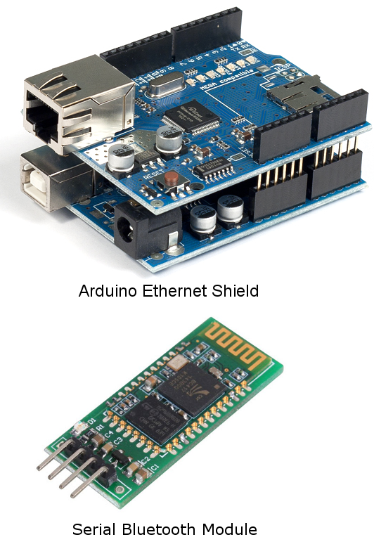
An Arduino can be connected to a network, and thus to the Internet, by using various networking modules, e.g., standard WiFi, wired Ethernet or Bluetooth, see Figure 1. Other custom solutions are also available, such as for example RF modules used to communicate in the 315MHz-2.4GHz frequency range. However, such modules do not use the standard WiFi protocols, therefore you can't use them for directly connecting your Arduino to the Internet, by simply using your WiFi router or repeater.
A simple solution for having an Arduino connected to a WiFi network, thus to the Internet, is to use an ESP8266 module. These modules are now widely available, with prices in the range of 2-8 EUR, including postage to the EU. Such a module is what we are going to use in this tutorial, and we intend to provide you with a guide on how to choose one, since multiple variants are available, how to update its firmware, since new versions are available almost every month, and how to use it for transmitting and receiving data by using standard Web technologies, such as HTTP(S).
Choosing an ESP8266 Module Version
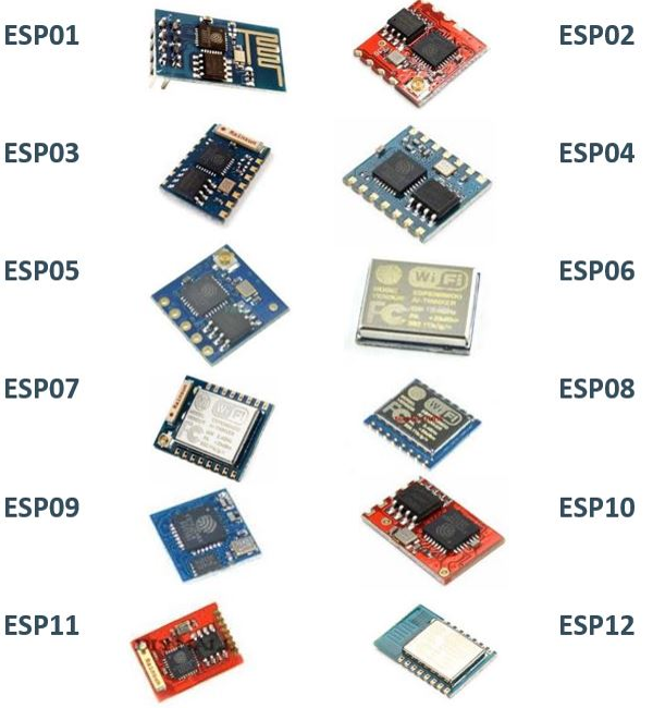
Multiple versions of the ESP8266 WiFi module are available, we are aware about 12 of them, as shown in Figure 2.
These modules use the 802.11b/g/n standard, operating at 2.4 GHz. This means, we can connect to a standard WiFi network, such as the one most of us have at home, provided by an WiFi router or access point (AP).
Having multiple variants of ESP8266 module, comes the question: "which one should I use ?". There is no perfect answer for this question, and it highly depends on what you are using the WiFi module for. These modules are not only a "blind" WiFi communication module, but are based on a MCU, which can be programmed and which have I/O pins, therefore it can do tasks similar with the ones available for the Arduino boards. Even more, the Arduino IDE supports ESP8266 programming, but details about this topic we'll discus in another tutorial. Regarding our question, there are three main reasons to consider when choosing an ESP8266 module:
- usability on a breadboard: most of the times we prototype on a breadboard, therefore we should be able to connect these modules to such a board. Some of the modules, such as ESP02, ESP03 and ESP05 (see Figure 2) are breadboard friendly, having a pitch of 2.54mm (the distance between two pins). Other modules, such as ESP07 or ESP08 have a pitch of 1.27mm, thus you'll only be able to use them with a breadboard when using an adapter. Last, other modules, such as ESP01 have a pitch of 2.54mm, but they have a two-row header, which makes it impossible to use it with a breadboard, because the implied short-circuit between the pins. Notice that some of the breadboard friendly modules have only a half-way pin connections, see ESP02 module from Figure 2. Such connections are somehow harder to solder, specially for a beginner. Our tip: plug the pin headers into a breadboard, align the module on top of them, then solder.
- flash memory size: this is very important to consider when choosing an ESP8266 module, because they come with permanent flash memory, which is usually in the range of 4MBit (512KB) up to 16MBit (2MB), but can go up to 128MBit (16MB). Starting with the firmware version 1.1.0 (released on June 2015), you'll need a module with at least 8MBit (1MB) flash size to burn the new firmware. Thus, pay attention when buy the module and be sure that you get one that has at least 8Mbit (1MB) flash size. In term of RAM and MCU frequency, they are mostly the same, so no need to worry about it. There are ways to improve the flash capacity, but for this you'll need good soldering skills to remove the old flash IC and solder the new one, and usually the price of the flash IC bought in small quantities is more than half of the ESP8266 module price, thus defeating the purpose. Excepting for the ESP06, ESP07, ESP08 and ESP12 modules, which have a metallic (hard to remove) cover over the CPU and flash IC, you can simply detect the flash size by reading the text on the 8 pin black IC soldered near the MCU (which is the square black IC with pins on all four sides). If the number on the flash IC starts with 25Q80 then you have a 8MBit sized one, while if it starts with 25Q40 then you have a 4MBit sized one.
- MCU features: these modules are driven by a low power 32-bit RISC CPU (Tensilica Xtensa LX106) running at 80 MHz. It has 64 KB of instruction RAM, 96 KB of data RAM and supports external QSPI flash - 512 KB to 4 MB (up to 16MB is supported). I has 16 I/O pins, from which one has 10Bit ADC capabilities, and supports I2C, I2S, SPI and UART communication protocols. All these features are quite important if you are using the ESP8266 module as standalone controller board. However, if the ESP8266 module is used as WiFi interface only, then you'll not need these features, and you can chose the cheapest and board with suits your needs.
Based on the above considerations, we chose to use ESP02 module, because it is small, breadboard friendly (even if is not very easy to solder the pin header) and it has a connector for a 2.4GHz WiFi antenna, thus allowing for a good WiFi range, even when used indoors.
Update the ESP8266 Firmware
Disclaimer: perform the tasks shown on this section on your own risk. If something goes wrong, it may be possible to have a "bricked" module, which can't be used anymore or requires special tools to repair.
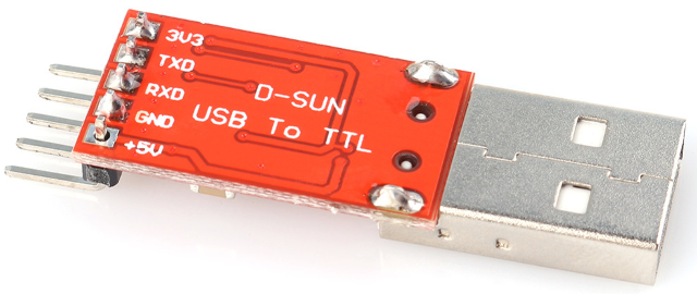
Normally, after buying an ESP8266 module, the first task is to ensure that it has the latest firmware, thus being able to use the latest features and having fixed various software related problems. But how do we know if the last firmware is burned into our ESP8266 module? To answer this question we need to connect the module to a computer by using a TTL module and a software, which allows us to communicate with the module and perform queries or provide commands. A TTL module (e.g. see Figure 3), see is a communication device that connects to an USB port of the computer and allows to map Serial protocol via the USB port. Its TX and RX pins connects to the RX and respective TX pins of the ESP8266 module (pay attention, the pins connection is twisted!). Such modules are quite cheap, having an approximate cost of about 2-3 EUR postage included in EU.
In Figure 4 and Figure 5 are shown the breadboard connection and the schematics of the circuit which allows us to have the ESP02 module communicating with a computer by using the serial port (UART communcation). A breadboard friendly power supply is used to provide the required 3.3V for the ESP8266 module. This specific one allows inputs in the range 5-12V and produce a steady 3.3V or 5V (a switch allows the selection) output, with a maximum current of 0.5A.
In addition, we need a software which allows us to have a user interface so we can send commands (or queries) to the module and see the module answer. While there are multiple software available for this purpose, we found Realterm as being very stable, free of charge and easy to use. Further in this tutorial we refer to Realterm when providing examples or screen shots related to this topic, but you are free to use others if you like, such as for example Putty.
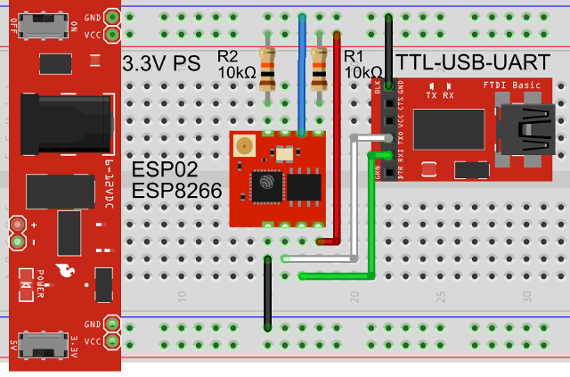
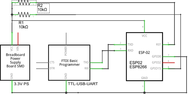
It may be observed that two of the ESP8266 module pins are connected to VCC (3.3V) via 3.3kΩ resistors. This is required, because the RST (reset) and CH_PD (power down) pins must stay high during the normal operation of this module. One can use Arduino I/O pins to control the state of these pins, thus having reset and power down features for a project that implies to use the ESP8266 module, and allowing for lower energy consumption when WiFi transmission is not required. The ESP8266 module is able to recover very fast from a "power down" state, the wake-up time being in the order of milliseconds. However, after resetting the module, may take up to two seconds to have the module booted and a few other seconds until WiFi line is ready to be used.
Important: the connection between the GPIO0 of the ESP8266 module and GND (see the blue wire in Figure 4) is required when the firmware needs to be updated. In all the other case, you should remove this connection, otherwise your module will not communicate via the UART port (RX/TX lines). Removing or connecting GPIO0 pin to GND should be done ONLY when the module receives no power, so first turn OFF the power supply connected to module, then connect or disconnect the wire (or jumper) between the GPIO0 to GND.
The USB-TTL module we use has a 3.3V UART interface, therefore is no need to have an additional voltage LC (level converter) module. Before doing the connections, check if your module has already this feature, by measuring (using a voltmeter) the voltage between the GND and TX pins of the USB-TTL module. If you read a voltage value under 3.5V, then it is safe to connect the RX and TX pins of the USB-TTL module directly to the ESP8266 TX and RX pins. If you read more than 3.5V then you need to use a LC module to convert the 5V to 3.3V and back between the RX and TX lines of the ESP8266 module and the USB-TTL module. Ignoring this advice may result in a broken ESP8266 module, so do it at your own risk!
Note: it is strongly recommended to use a stable 3.3V power supply that is to provide current in excess of 500mA (0.5A). The ESP8266 module is in general power efficient, but during the data transmission, it may have peaks of up to 500mA. Powering it from the 3.3V rail of the Aruino board or from the 3.3V rail available for some USB-TTL module is NOT recommended and will very likely result in destroying the 3.3V voltage regulator of your Arduino board or of the USB-TTL board. We use a breadboard friendly power supply, able to provide 3.3V and 5V (a switch allow the selection) at up to 500mA (see Figure 4). This specific power supply cab be found very cheap, having prices of about 1-3 EUR postage in EU included.
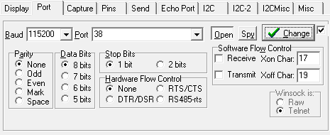
After you have downloaded and installed Realterm, start it and select the baud rate (normally this defaults to 115200 for most of the ESP8266 modules we bought over the last 6 months) and the COM port (which in our case is 38, but may be different for you, so better check). Last, push the "Open" button, to create a Serial (UART) connection. If the "Open" button was already pushed, then push it again to its OFF state it and push it back to its ON state. Also, check Figure 6 for additional information.
Note: Realterm is highly configurable via command line parameters. Check the command line configuration parameters documentation for making your settings permanent (e.g., to have the program started with the COM port and baud-rate already set to whatever you like) or for having various other configurations.
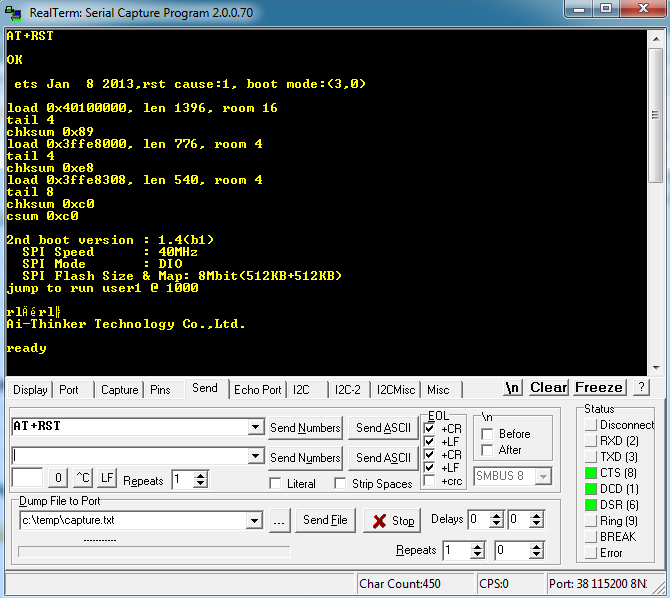
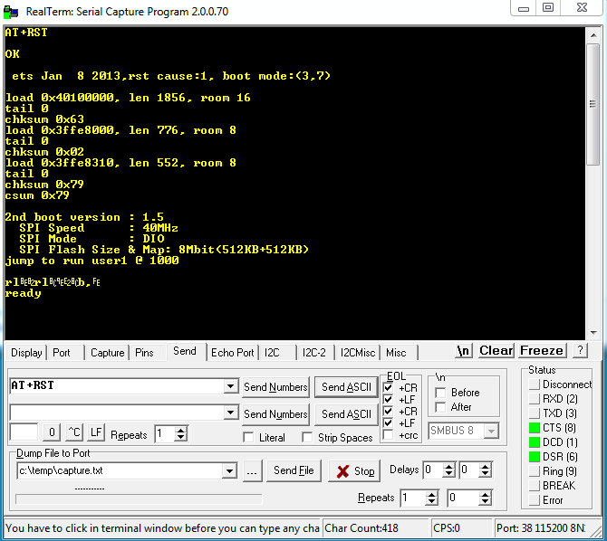
At this moment we are ready to communicate with the ESP8266 module. First operation we like to perform is a reset, so we are able to see that the module reacts to our commands. For this, go to "Send" tab in Realterm UI and write "AT+RST" on the first text input box. Please check the "+CR" and "+LF" boxes located on the right of the first text input box, thus allowing to send a CR and LF chars at the end of the command, allowing the ESP8266 module to detect a "command end" limiter. You should see a result similar with the one shown in Figure 7, but some of the response text may differ in your case because of different firmware versions.
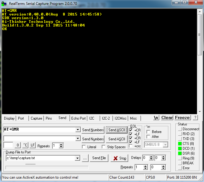
Our initial purpose was to check if we have (or not) the latest firmware burned int our ESP8266 module. For this, following the same procedure as for "AT+RST" command, we send the "AT+GMR" command. Tee result we obtain is shown in Figure 8 but you may have a different one, because of a different firmware version burned into your module.

As shown in Figure 8, the SDK firmware version of our module 1.3.0 and the AT version is 0.40.0, which are quite old (see also the date, is 8 August 2015!). Check if there is any available firmware update by navigating to http://bbs.espressif.com/ and look at the "SDK" section. We found that the current available firmware update is SDK version 1.5.3 and the current AT version is 1.1.0 (dated 16 April 2016).
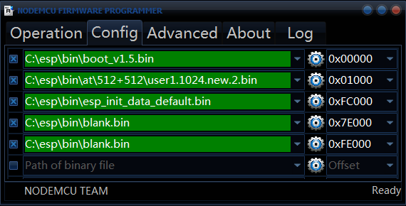
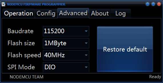
Download the firmware following the links provided in the SDK download page, then unzip the archive somewhere on your PC hard drive. Open the ESP8266Flasher tool, available as download in the archive attached to this tutorial. Now follow the instructions shown in Figure 9, Figure 10 and Figure 11 to configure the tool for firmware update. Notice that in Figure 10, we have selected 1MB because our ESP02 module has a 8MBit (1MB) flash IC, but you should do the appropriate selection for your module if the flash IC is different. However, a flash IC with a size smaller than 1MB will not work, since the current firmware version is to big to fit. Such a module cannot be upgraded to a firmware version greater than 1.1.0 (which is quite old and misses a lot of features, so go and break your piggy bank and buy an appropriate ESP8266 module!).
Note: the ESP8266 firmware update tool, as well as the current version of the ESP8266 firmware is part of the download archive we provide with this article. However, new firmware versions may be released at anytime, so better check the http://bbs.espressif.com/ for being sure that you get the latest version.
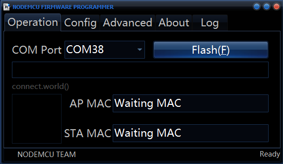
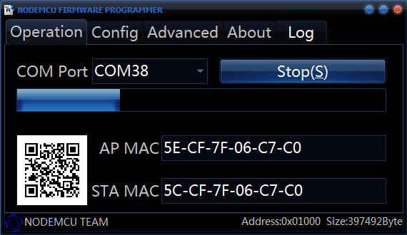
Last, start the firmware update by pushing the "Flash" button, shown in Figure 11. If all was correctly configure, you should see now the "AP MAC" and "STA MAC" fields (shown in Figure 11) filled in with values (as shown in Figure 12), and the blue bar starts to fill in, showing the progress (see Figure 12).
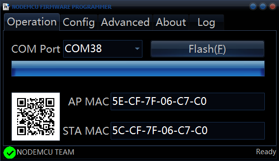
The update may take about a minute or two, and at the end, the ESP8266Flasher UI should look similar with Figure 13.
At this point, you'll need to power down the ESP8266 module (disconnect the power supply), and remove the connection between the GPIO0 pin and GND, so the module does not enter firmware upgrade mode when powered up. Missing this step results in a non communicative module, therefore not responding to commands and looking as a broken one, software wise.
Start the Realterm, make the port configurations (discussed earlier in this section) and run the "AT+RST" command and then the "AT+GMR" command and check the results. If all went well, you should see results similar with the ones shown in Figure 14 and Figure 15.
Note: the "Display" tab of the Realterm UI provides useful settings for selecting how the data is displayed. Normally, you'll want to select "Ascii" or "Ansi" as the value of the "Display As" parameter. In addition to normal characters, from the ASCII table, the "Ascii" mode shows also the special chars, such as CR and LF, which are important when using Realterm to debug or control ESP8266 module.
Use Arduino and HTTP(S) to Access Online Services via an WiFi Network
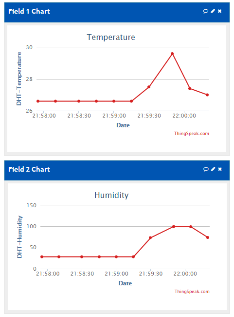
In this section we are going to use Arduino UNO, ESP02 WiFi module (remember, we chose to use this specific one out of all existing variations) and the DHT22 temperature and humidity sensor. With the ESP02 module we are going to connect to a WiFi network, thus gaining access to internet. Using a free thingspeak.com account, we store the temperature and humidity values, with the purpose of having charts that shows the evolution over time. We send a sample every 15 seconds, since it is highly improbable to have changes of temperature and humidity values faster than this, which also provides a lower power consumption, since the ESP8266 modules are quite power efficient in "stand-by" mode, but this changes a lot when data is transmitted over WiFi.
It may be useful to have also a USB-TTL module near you, so in case of the case that your ESP8266 module seems irresponsible, you can try to provide commands directly via Realterm software, as discussed earlier in this tutorial.
Hardware Configuration
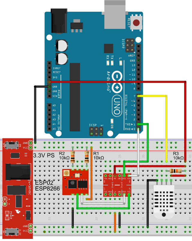
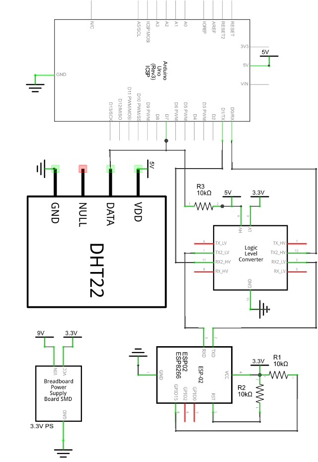
As shown in Figure 16 and Figure 17, for this project we need the following components:
- An Arduino UNO board, but you can use almost any Arduino board, with minimal or no modifications.
- An ESP02 WiFi module, but you can also use any of the 12 available versions, just remember to update the firmware.
- A DHT22 temperature and humidity sensor, but if you like, DHT11/21 or LM35 are as good, you'll just need to adapt your code related to sensor reading.
- A voltage LC module, that allows the communication between Arduino and ESP02 module, but you can skip this in case you are using a 3.3V Arduino board (e.g., Arduino DUE).
- A voltage regulator module, that uses USB or a power brick to provide the 3.3V@500mA required by the ESP02, and most of the other ESP modules.
- Three 10k resistors, used to PULL UP the DHT22 data pin and the RST and CH_PD pins of the ESP02 module.
In addition, an USB-TTL module may be useful for debugging, but this is not required for the functionality of the circuit. Notice that the connection between GPIO0 pin of the ESP8266 module and GND is dropped, that being only required for the firmware update. If you still have that connection, now is the case to disable it, because your module needs to boot up, and that is not the case as long as GPIO0 is connected to GND. You should let GPIO0 pin floating (not connected).
SoftwareConfiguration
In this section we'll learn how to use the AT commands set for being able to connect to a WiFi network, then using TCP connect to a live server, and last, send the temperature and humidity values to thingspeak.com for being stored and having displayed them as a chart.
Note: all the source code, including the required libraries are included in the zip archive available for download as part of this article (check the article head), but we encourage you to visit our github.com project page where you can download the latest changes, updates and fixes for this code and much more.
First, you'll need to setup a free account at thingspeak.com. Then, in the "Channel Settings" menu enable "Field 1" and "Field 2", and give them some human readable names, such as "DHT-Temperature" and "DHT-Humidity". Then, navigate to "Api Keys" menu and copy the "Write API Key" value and paste it on the ESP8266_DHT22.ino as the value of DATA_SERVER_API_KEY constant. The file ESP8266_DHT22.ino is located under under examples/ESP8266/ESP8266_DHT22 folder. Remember to replace also WIFI_SSID and WIFI_PASSWORD constants values with your own WiFi network credentials.
Second, you'll need to copy the DHTxx and ESP8266 folders, located under libraries sub-folder, into your libraries sub-folder of the Arduino IDE software. This is required because we'll use these two libraries with our example code.
Lets have now a look at the example code, part of the examples/ESP8266/ESP8266_DHT22/ESP8266_DHT22.ino Arduino sketch. Like with any Arduino porgram, we'll need to include the library headers, in our case these are DHTxx.h and ESP8266.h. We also define a constant for the I/O pin used to communicate with the DHT22 sensor, and a set of constants that stores the WiFi credentials (SSID and password), thingspeak.com server address (api.thingspeak.com), the TCP port used for connection, the request path and the thingspeak.com "Write API Key" (required for being able to write data).
#include <dhtxx.h>
#include <esp8266.h>
#define DHT_PIN 7

// WiFi authentication data
const char* WIFI_SSID = "your-wifi-ssid";
const char* WIFI_PASSWORD = "your-wifi-password";

// data server address and port
const char* DATA_SERVER_ADDRESS = "api.thingspeak.com"
const uint8_t DATA_SERVER_PORT = 80;

// data to be sent to the server
const char* DATA_SERVER_API_KEY = "your-thingspeak-write-api-key";
char* DATA_SERVER_PATH = "/update";
</esp8266.h></dhtxx.h>
Further, we have to create the Dht and ESP8266 objects, responsible for the communication with the DHT22 sensor and ESP8266 WiFi module.
Dht dht(DHT_PIN, Dht::TypeEL::DHT22);
ESP8266 esp(Serial);
The Arduino board and the ESP8266 module communicates via the serial port, thus we use the Serial object as the middle-ware. The Serial global object, which is Arduino specific, is provided as parameter to the ESP8266 object and used internally to read and write data, as well as to deal with the incoming data streams and extract the relevant information.
The setup method takes care of the Serial port initialization (communication is made at 115200bps). In addition, it creates a loop while trying to connect the ESP8266 module to the specified WiFi network (credentials are provided by the WIFI_SSID and WIFI_PASSWORD constants).
void setup() {
  Serial.begin(115200);
  esp.atCwmode(ESP8266::WiFiMode::STA);
  while (esp.atCwjap(WIFI_SSID, WIFI_PASSWORD) != ESP8266::Error::NONE);
};
The atCwjap method, part of the ESP8266 library, is responsible with the WiFi connection for the specified WiFi network. This method is the equivalent of AT+CWJAP="wifi-ssid","wifi-password" command, which we can send to the ESP8266 module, e.g., by using Realterm. The library we are using, contains a set of methods, most of them being a one-to-one mapping of a specific AT command, and the method name is the AT command name (e.g., AT+CWJAP has the equivalent method atCwjap). However, notice that this library does not covers the complete set of available AT commands.
It is important to know that the ESP8266 module may work in three different modes: client (STA), access point (AP) and both combined (AP+STA). The AT+CWMODE command allows to set one of these modes, and the used values are: 1 for STA, 2 for AP and 3 for AP+STA. E.g., AT+CWMODE=1 sets the module in client (station) mode. Our ESP8266 library has an equivalent method, atCwmode for this command. It takes as parameter an enumeration literal value, ESP8266::WiFiMode::xxx, where xxx = {STA, AP, AP_STA}. Since we use the WiFi module to connect to a network, she STA mode is the most appropriate, and we set this in the setup method. It will also work if AP+STA mode is used, but this have some security implications, because the WiFi module becomes also an WiFi access point that has internet access, and unless you know exactly what you are doing, it may open serious security back-doors in your network.
In the loop method (remember, this method executes again, and again as long as the Arduino receives power) we check if we have a WiFi connection, and if that is true, we perform a DHT22 sensor reading and sent it to thingspeak.com by using the sendDataToServer method, that we'll discuss further. We do this with a periodicity of 15 seconds, thus the delay(15000) call. Notice that the real time between sending data is larger, since various other delays occurs in the code, such as for the TCP connection, data sending, and so on.
void loop() {
  if (!checkWiFi()) return;
  Dht::Result result = dht.read();
  if (result.status == Dht::StatusEL::OK)
    sendDataToServer(result.temperature, result.humidity);
  delay(5000);
};
The checkWifi method simply sends an AT command and waits for an OK, which the ESP8266 module normally sends as response. This command is not really supposed to do something, but just to have a simple way to detect if a serial communication with the module exists or not.
boolean checkWiFi() {
  if( esp.at() == ESP8266::Error::NONE) return true;
  return false;
};
The sendDataToServer method is responsible with four operations:
- creates the HTTP request, by using a template, discussed later in this tutorial;
- opens a TCP connection on port 80, with the specified server (see the
DATA_SERVER_ADDRESSconstant); - sends a GET request to the data server;
- finally, closes the TCP connection.
void sendDataToServer(float temperature, float humidity) {
  char data[64] = {0};
  char *pData = data;
  createDataFromTemplate(pData, temperature, humidity);
  esp.atCipstartTcp(DATA_SERVER_ADDRESS, 80);
  esp.atCipsendHttpGet(DATA_SERVER_PATH, data);
  esp.atCipclose();
};
An example of a HTTP GET request that we like to submit looks as follows:
GET /update?api_key=22.7&field1=%s&field2=35.5 HTTP/1.0
We see that some static parts are used (the HTTP method name, the request path /update and the HTTP version specification), but also some parts that are changing, such as the values of field1 and field2 parameters, corresponding to temperature and humidity values. We'll turn the parameter part of the request into a template, where the dynamic values are replaced at the request time with specific temperature and humidity quantities. For this, we define a template char pointer (you can thing on it like being a string).
const char DATA_TEMPLATE[] PROGMEM = "?api_key=%s&field1=%s&field2=%s";
Some magic happens here, because of the keyword PROGMEM. That is not really related to the template, but to the way on which the "template string" is stored by the Arduino MCU. Normally, all strings are stored in the RAM, thus keeping the RAM occupied with data that is only rarely used. The PROGMEM variable modifier informs the compiler that we like to store this value in FLASH (remember, we have FLASH sizes with an order of magnitude greater than RAM!). The problem is now, that we can't just simply read the variable and expect to have the value there, because what it really stores is the start address of the FLASH memory where the data was stored. For this reason, we created the getPMData (get program memory data) method to extract the real data from FLASH. Notice that this method comes with the ESP8266 library and is used intensively to deal with the static strings involved by the communication with the ESP8266 module. This method takes three parameters: 1) the defined PROGMEM variable; 2) a char pointer with sufficient allocated memory to store the data you need to read; and 3) a reference to an uint8_t variable that will be set to a value representing the length of the data that was read from FLASH.
In the createDataFromTemplate method, we take care to replace the parameters, represented by %s (denoting a string parameter), into real values.
void createDataFromTemplate( char *&data, float temperature, float humidity) {
  char buffTemp[6] = {0}, buffHum[5] = {0}, tmpl[32] = {0};
  char *pTmpl = tmpl;
  uint8_t templateLen = -1;
  // read template from PROGMEM
  getPMData( DATA_TEMPLATE, pTmpl, templateLen);
  // create data string from template by replacing
  // parameters with their actual values from sensors
  sprintf( data, pTmpl, DATA_SERVER_API_KEY,
    dtostrf( temperature, 0, 1, buffTemp),
    dtostrf( humidity, 0, 1, buffHum));
};
Using the getPMData method we read the template from FLASH. Further, using sprintf we replace the specified parameters (i.e., which starts with the % symbol) with concrete values. The dtostrf method allows to transform the float values that we have for temperature and humidity into strings, used then to fill the template variables. Notice, that sprintf is able to deal directly with numeric variables, but unfortunately its version available for the Arduino sketches lacks this functionality, thus we also need to use dtostrf.
Replace the constant values (i.e., WIFI_SSID, WIFI_PASSWORD, DATA_SERVER_API_KEY and so on) with your own values, then write the sketch into your Arduino. If all went fine, you should now check your account and access the "Private View" tab of your thingspeak.com account. In our case, for a small set of values, we obtain the charts shown in Figure 18. Remember, that we only set data once every 15 seconds, meaning that it can take a while until you'll see something on your thingspeak.com chart.
Some Points of Attention
It is important to use a good quality power supply, both for your Arduino board (if not powered via USB) and the ESP8266 module. A low quality power supply may have unknown effects, and may produce behaviors like unwanted resets of the devices. If your ESP8266 module seems to be unstable, i.e., often resets by itself, then it is very likely that you have an issue with the 3.3V rail provided to the module. You can try to add a 1000µF electrolytic capacitor in parallel with an 0.1µF ceramic capacitor to the 3.3V rail. If this does not improve the module behavior, then try to replace your power supply. If an oscilloscope is available, you can observe the behavior of the 3.3V rail.
When using the ESP8266 module with a device that runs the UART communication on 5V rail (e.g., Arduino UNO and most of the other Arduino boards), then you need to use a voltage LC (level converter) between the RX and TX lines of the ESP8266 modules and the TX and RX lines of the paired device. Also, remember, the RX and TX lines are twisted between the two devices implied in the UART communication.
While the ESP8266 is a really nice and cheap module, the current version is not rock solid in terms of stability, thus you may observe strange behaviors sometimes. It may help to reset the software configuration to its default state, by using the "AT+RESTORE" command. After that, you should configure the module again, with respect to all parameters you've been set before the reset (e.g., WiFi connection, client or AP mode, etc). If your module still misbehaves, then a better power supply may help. Also, be sure that you didn't wrote a firmware with a version over 1.1.0 on a module that only has 4Mbit (or less) flash size, because you may completely brick your module.
Sometimes, TCP or UDP connections made via this module are not stable or you may even get connection refused errors. In this case, you should try a few more times to be sure that it is really a problem, since in multiple cases this is just a temporarily problem and can be solved by retrying, resetting or power cycling the module.
Periodically check the temperature of your ESP8266 module, simply by putting your finger on the CPU IC. If it feels hot when touched, then something may be wrong. Usually a hot CPU on the ESP8266 module means that the module receives more than the 3.3V required on the power line or on the RX and/or TX lines. Check the voltage, and make sure that this is not the case. If this is not the case, the high temperature may be due to high WiFi activity. While this is not unusual for these modules, make sure that the module is on a place with environment temperature under 30°C to avoid overheating and damaging the CPU.
When using the module in AP (access point) or STA+AP (station and access point) modes (that is, AT+CWMODE=2 or AT+CWMODE=3), make sure that you set a good password, otherwise you may have "spy eyes" on your network and may even result in security breach of your entire enterprise network! To check if you are in either AP or STA+AP mode, run the "AT+CWMODE?" command and check which value it returns (+CWMODE:1 means STA mode, +CWMODE:2 means AP mode and +CWMODE:3 means STA+AP mode).
Next Tutorial: Part 4 - Control the Environment by Using Actuators
In this tutorial we'll learn how to use Arduino to produce environment changes. Specifically, we'll use relays to turn ON/OF lights, miniature water pumps to ensure the correct soil moisture for our beloved room plants and a DIY PWM actuator to adjust the intensity of a dimmable LED strip, used to produce ambient light on a room.
The release date of the 4th part is: before 24 May 2016.