
WoT with Arduino for Beginners: Part 2 - Connecting to the Real World via Sensors
5.00/5 (12 votes)
Learn how to develop Arduino-based apps for the Web of Things (WoT). This second part of a series of tutorials shows how to read analog and digital sensors with the help of Arduino.
In this multi-part tutorial we show how to develop Arduino-based apps for the Web of Things (WoT). This second part shows how to read data with the help of analog or digitally controlled sensors. In the following parts of this tutorial, which will appear every 1-3 weeks, we discuss how to control actuators and how to connect them all together in a Web of Things (WoT) network. Using standard Web technologies, such as HTTP and Web Sockets, we can then access the data or provide commands to the WoT nodes. As a newbie, it is helpful if you already have some basic C/C++ programming knowledge and understanding of some Web standards and programming languages, such as HTML and JavaScript.
This tutorial is part of our WoT learning materials published on web-engineeering.info.
You may first want tor read the previous part of this tutorial series:
The next parts are:
Disclaimer: working with electricity is dangerous. For this project we'll use 5V, which is safe for the human body under any environment conditions. However, the low voltage may be obtained from a mains connected power brick, and therefore we highly recommend you to take safety precautions and to use a trustful brand for the power supply. We cannot be held responsible for any caused damage! Do it at your own risk and/or ask help from an electronics engineer. In case you are using the USB connector from your PC to power the Arduino board, be aware that short-circuits which may occur on the Arduino board may also have a negative impact on your PC!
Credits: some of the images from this tutorial are created by using Fritzing, a nice electronics modeling tool for beginners.
What is a Sensor ?
A sensor is a device that is able to capture a quality (property) of the environment, within its detection radius, and provides, in some form, a quantity value representing the quantitative characteristics of that property. There are two main sensor categories: electronic sensors or mechanical sensors.
Examples of devices consisting of one or more sensors:
- electronic sensors: digital thermometers, weather stations or alcohol level testers;
- mechanical sensors: water levels using balloons and graded bars, tire pressure testers found in gas stations, spring based pressure sensors found in some vices or force sensors found in manometer tools.
Usually, we also call sensor a collection of detectors, such as measuring temperature and humidity in the same time. A detector is an atomic sensor, able to measure one specific quality. Therefore, a sensor may consist of either one or more detectors.
Further in this tutorial we only discuss about electronic sensors/detectors: their output is an electric signal, that can be captured and interpret as the quantity of the environment measured quality (property). We'll use Arduino UNO board as interface (or controller), but most of the other Arduino boards (Nano, Micro, MEGA2560, etc) works as well with the provided code examples, without any or with very minor changes.
Digital Sensors
A digital sensor is a sensor that uses a digital communication interface. Such an interface can be a standard one, such as I2C, SPI or UART, but can also be a custom one, such as a stream of HIGH and LOW signals (also known as pulses), which are then interpreted as binary data. Custom digital interfaces may also refer to simply measuring a pulse for an amount of time and interpreting its length as the received information. Last but not least, some digital sensors are only providing a HIGH (or LOW) signal, when an event occurs, such as a intrusion detection sensor.
In this tutorial we discuss the DHT11/DHT22 humidity and temperature sensor as well as the HC-SR04 distance measurement sensor, both using a custom digital interface.
Measure Temperature and Humidity with a DHT11/DHT22 Sensor
It is fairly simple to measure temperature and relative air humidity with the help of DHT11, DHT21 or DHT22 sensors. Each of those consists in fact of two detectors in a single package, and with a single 1-Wire custom digital communication interface. The main differences between these sensors are the measured ranges and their accuracy and resolution properties, as shown in the table Table 1.
These sensors are fairly low priced, and in EU you can buy a DHT11 sensor for about 3EUR, a DHT21 for about 4EUR and a DHT22 for about 5EUR, postage included. The price can be cut in less than half when you are willing to order it online from China (e.g., by using eBay), but be warned, the time to receive it in EU is usually from three to six weeks, sometimes even longer.
| DHT11 Temperature | DHT11 Air Humidity | DHT21/HM2301 Temperature | DHT21/HM2301 Air Humidity | DHT22/AM2302 Temperature | DHT22/AM2302 Air Humidity | |
|---|---|---|---|---|---|---|
| Range | [0, 50]°C | [20, 90]% | [-40, 80]°C | [0, 100]% | [-40, 125]°C | [0, 100]% |
| Accuracy | ±2°C | ±5% | ±1°C | ±5% | ±0.2°C | ±2% |
| Resolution | 1°C | 1%RH | 0.1°C | 0.1%RH | 0.1°C | 0.1%RH |
| Operating voltage | [3.3, 5.5]V | [3.3, 5.5]V | [3.3, 6]V | [3.3, 6]V | [3.3, 6]V | [3.3, 6]V |
| Operating current | [1.2, 2]mA | [1.2, 2]mA | [1.3, 2.1]mA | [1.3, 2.1]mA | [1.3, 2.1]mA | [1.3, 2.1]mA |
| Download datasheet | Download datasheet | Download datasheet | ||||
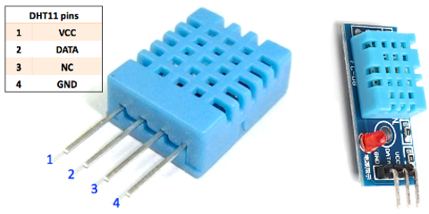
DHTxx sensor may come with or without a breakout board, which allows not only to fix the sensor with a screw in a fixed place, but also usually have a LED to indicate that the sensor receives power, and most of them provides a PULL UP resistor, which otherwise you have to add between their DATA and VCC pins. A PULL UP resistor has usually a value between 2kΩ and 20kΩ (most common values are 4.7kΩ and 10kΩ), and it connects the corresponding data line to VCC, thus the line stays at VCC level as long there is no other activity from the micro-controller, to pull the data line to LOW. Figure 1 shows variations of DHT11 sensors and Figure 2 shows variations of DHT22 sensors, with or without a breakout board, as well as the pin-out (pins configuration).

Hardware Configuration
Figure 3 shows how to connect a DHTxx sensor to an Arduino UNO board, and Figure 4 shows the electronics schematics. Notice the third pin of the sensor is not connected and all three variations of this sensor have the same pin-out.
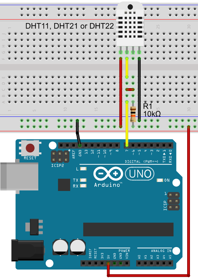
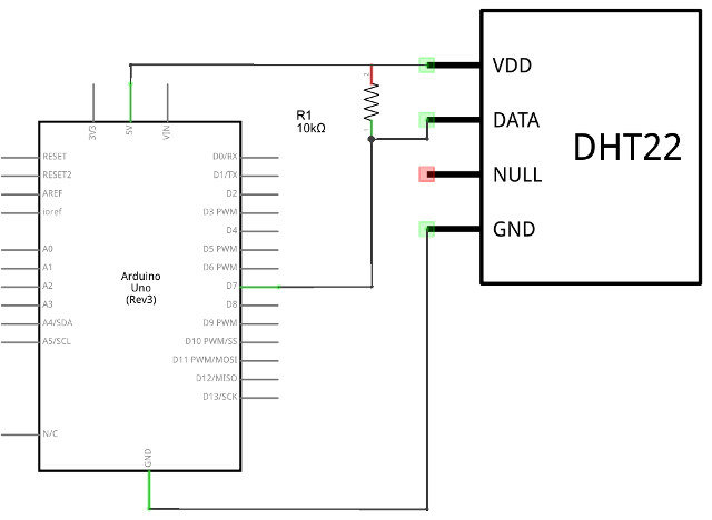
Note1: if we use a DHTxx sensor without a breakout board that includes a PULL UP resistor, then we'll need to add a 10kΩ one between the VCC line and the DATA pin. If the PULL UP resistor is missing, the received data may be corrupted or may be no transmission.
Note2: in some diagrams, the VCC pin is also noted as VDD, but its meaning does not change.
Software Configuration
Its now the time to query the sensor and obtain temperature and humidity data. For this you'll need to add the DHTxx library to your Arduino IDE libraries collection. Download the DHTxx library from github and copy the folder DHTxx into your libraries sub-folder of the Arduino installation folder. If the Arduino IDE was started before, you have now to close it and start it again.
To "load" the DHTxx library into our Arduino sketch, we use the #include directive. Then, we create an instance of the Dht class (defined by the library), which takes care of the communication with the DHTxx sensor. Its constructor has two parameters: the pin number used to communicate with the sensor (the Arduino UNO digital pin 7 in our example), and the sensor type used (DHT11, DHT21 or DHT22), defined by the Dht::TypeEL enumeration. While the DHTxx sensors are using almost the same data encoding during the communication, there are also slight differences, which require special attention inside the library code. Explicitly, one of Dht::TypeEL::DHT11, Dht::TypeEL::DHT21 or Dht::TypeEL::DHT22 can be used as the second parameter of the constructor, depending on your sensor choice.
#include <dhtxx.h>
#define DHT_PIN 7

Dht dht(DHT_PIN, Dht::TypeEL::DHT22);
Since we like to see the read temperature and humidity values, we'll use the Arduino serial communication capabilities, in combination with the Arduino IDE serial monitor tool, which you can open by using the "Tools > Serial Monitor" menu. This additional code is only required for being able to visualize the information, but has nothing to do with the sensor, or sensor communication. The DHTxx sensor requires some initialization time, which is usually about two seconds, thus a delay of two seconds is added in the setup method.
void setup() {
  Serial.begin(115200);
  delay(2000);
};
Last, we use the Dht::read method, to inquire temperature and humidity information from the sensor. A Result structure is provided in return, and it has three properties: temperature, humidity and status, which should be Dht::StatusEL::OK if no communication errors took place. We use a delay of five seconds between two readings.
void loop() {
  Dht::Result result = dht.read();
  if (result.status == Dht::StatusEL::OK) {
    Serial.print("Temperature: ");
    Serial.println(result.temperature);
    Serial.print("Humidity: ");
    Serial.println(result.humidity);
  } else if (result.status == Dht::StatusEL::CRC_ERROR) {
    Serial.println("CRC error! ");
  } else {
    Serial.println("Timeout error! ");
  }
  delay(5000);
};
Note: DHTxx sensors can be read no faster than once every two seconds. Not following this rule results in no communication with the sensor or communication timeouts.
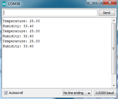
If all went well, and you have used an DHT21 or DHT22 sensor, you should see the Serial Monitor window showing information similar with Figure 5. One can observe slight differences between readings (like 0.2°C between the temperature values), but that is just fine, and are the result of the sensor accuracy.
If you are interested in more information about the low level communication with the DHTxx sensor, then you should have a look at the DHTxx library code (files DHTxx.h and DHTxx.cpp) which contains detailed code comments. Also, check the information provided in the DHTxx library github project page.
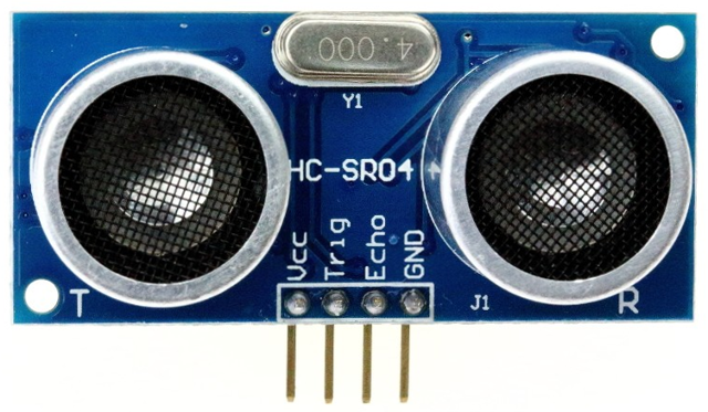
Measure Distance with HC-SR04 Ultrasonic Sensor
In multiple projects, measuring distance is an important aspect. Imagine a "self-driving" robot (or car) project, where detecting obstacles, thus measuring distance between the robot and any possible nearby objects, is one of the main tasks. Fortunately there is a easy and cheap way to achieve this, with the help of an ultrasonic based distance measurement sensor, such as HC-SR04, shown in Figure 6. These sensors uses high frequency sound pulses (40KHz or more) and measure the time required by the sound to travel forth, and back if it is bounced by an nearby obstacle. Internally, a timeout is used to detect if an object exists or not in the sensor range (which for HC-SR04 is about 4m). In Table 2 are shown the main characteristics of a HC-SR04 sensor.
Variations of this sensor, using the UART communication interface (i.e., HC-SR03) can be found on the market. Usually, they are more expensive (the price is double or more), and the communication protocol required to communicate with such a sensor, especially RAM resources, are higher.
HC-SR04 sensors are fairly low priced, and in EU you can buy one for as low as 3EUR including postage. If you are willing to wait up to six weeks, it is possible to buy such sensors from China (e.g., by using eBay) for about 1EUR per piece, including postage.
| Range | Detection Angle | Accuracy | Resolution | Operating voltage | Operating current |
|---|---|---|---|---|---|
| [2, 400]cm | 30 degrees | 3mm | 1mm | [4.5, 5.5]V | [12, 18]mA |
| Download datasheet | |||||
Hardware Configuration
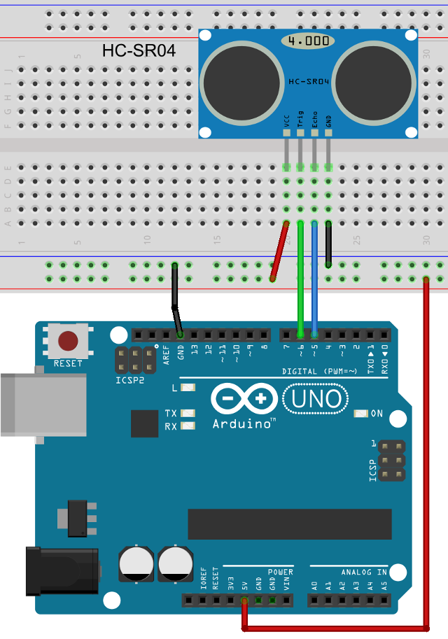
Connecting the Arduino board with the HC-SR04 sensor is really easy. First, you'll need to provide power to the VCC and GND pins. Second, chose two Arduino pins (use digital ones while the analog pins we need for other purposes) to be used in the communication with the sensor. One pin represents the "trigger", informing the sensor that we like to read the distance, and the other one represents the output from sensor, also known as "echo", providing a pulse of a specified length, mapped then to a distance value.
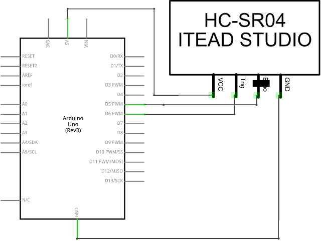
In Figure 7 is shown how to wire the sensor to an Arduino UNO board, but the same apply to almost any other Arduino boards. Figure 8 shows the electrical diagram of the circuit.
Software Configuration
Reading the distance with a HC-SR04 sensor requires to download from github and import the HCSR04 into your Arduino IDE. For this, you'll need to copy the folder HCSR04 into your libraries sub-folder of the Arduino installation folder. If the Arduino IDE was started before, you have now to close it and start it again.
Use the #include directive to "load" the library into your Arduino sketch. Create an instance of the HCSR04 class, which takes care of the communication with the sensor. The constructor has two parameters: the pin number used to inform the sensor that we want to read the distance, known as the trigger pin (the Arduino UNO digital pin 7 in our case), and the pin number used to read the sensor response, known as the echo pin (the Arduino UNO digital pin 5 in our example).
#include <hcsr04.h>
#define TRIGGER_PIN 6
#define ECHO_PIN 5

HCSR04 hcsr04(TRIGGER_PIN, ECHO_PIN);
Since we want to test the sensor and check the distance it reads, we'll use the Arduino serial communication capabilities, in combination with the Arduino IDE serial monitor tool (use the "Tools > Serial Monitor" menu) to show the sensor readings. This additional code is only required for being able to visualize the information, but has nothing to do with the sensor, or sensor communication. The HC-SR04 sensor requires some initialization time, which is usually about one second, thus a delay of one second is added in the setup method.
void setup() {
  // Start serial communication, used to show
  // sensor data in the Arduino serial monitor.
  Serial.begin(115200);
  // Wait for the HCSR04 sensor to settle.
  // This usually needs about one second...
  delay(1000);
};
Use the HC-Sr04::read method, to inquire distance measurement from the sensor. By default, the distance is measured in centimeters. If you need the distance in millimeters, meters or kilometers, use the HCSR04::read(HCSR04::MetricsEL::xx) method instead. The value of the parameter can be one of: HCSR04::MetricsEL::mm, HCSR04::MetricsEL::cm (default), HCSR04::MetricsEL::m or HCSR04::MetricsEL::km.
void loop() {
  float distance = hcsr04.read();
  if (distance > 0) {
    Serial.println(distance);
  } else {
    Serial.println("Error reading the sensor!");
  }
  // continuously read the sensor, ~10 times/s
  // Note: may be much less than ~10 times/s because reading
  // the sensor and checking the timeout may take up to 50ms
  delay(100);
};
Note: while in theory you can make hundreds of readings per second with this sensor, the practice learn us that you can take under ten reliable readings every second second. This is due to Arduino capabilities but also to sensor internals, driven by another micro-controller.
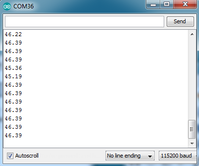
If all went well, you should see the Serial Monitor window showing information similar with Figure 9.
If we've got your attention and you want to know more about how exactly the software communicates with the sensor and maps the detected pulse length into a distance value, please have a look at the library code which is commented in the smallest details.
Analog Sensors
Analog sensors provide information about the measured quality as a voltage level, or other equivalent form, e.g., resistance of current. Using various electronics laws and equations we can interpret these values as a quantity of the measured quality. Examples of such sensors are photo resistors, rain or soil moisture sensors, providing the information into the form of "resistance". Other sensors, such as LM35 analog temperature sensor, directly provides a voltage level that can be translated into temperature value using a liner function.
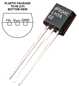
Measure Temperature with LM35 Analog Sensor
LM35 sensor, shown in Figure 10, is a very cheap way (it costs under one EUR for one piece) to measure the environment temperature, used in combination with any device that is able to read voltage in the millivolts range. That means, we can even use a multi-meter (a device able to measure voltage, resistance, current, etc) to measure the temperature, without the need of having an additional micro-controller. However, in this tutorial we show how to use an Arduino UNO to do the measurement. These sensors comes in multiple variations, from which the most known is LM35DZ. Table 3 shows the most important characteristics. Other versions are different in ranges, accuracy or supply voltage values.
| Range | Accuracy | Resolution | Operating voltage | Operating current |
|---|---|---|---|---|
| [-40, 110]°C | ±0.25°C | 0.2°C (= 2mV Output) | [-0.2, 35]V | [60, 100]µA |
| Download datasheet | ||||
The linear function used to translate sensor output voltage in °C of temperature is: f(x) = 100x, where x is the sensor voltage output in volts and f(x) is the temperature in °C. In other words, for every 1°C, the output voltage of this sensor is 10mV, e.g., 220mV output means a temperature value of 22°C.
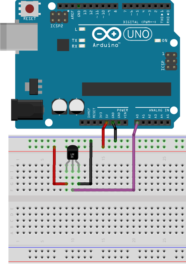
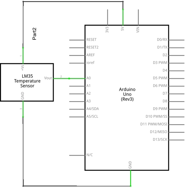
Hardware Configuration
Connecting a LM35 sensor to Arduino UNO is very simple, as shown in Figure 11. Just connect the VCC pin to 5V (obtained from Arduino UNO 5V pin), the GND pin to Arduino UNO ground and the output pin to one of the analog pins of the Arduino UNO board, annotated with A0...A5. In our example, we use A0. No additional components are required. Figure 12 shows the schematics of the circuit.
Software Configuration
Ardunio UNO and most of the arduino boards comes with a feature known as ADC: Analog to Digital Converter. That is, connecting a voltage source to one of the ADC capable pins, we can measure the applied voltage value.
Note: you should NOT try to measure voltages over VCC, so 5V in our case, with any ADC pin, because you'll burn your Arduino micro-controller. Also when using a 3.3V Arduino board, the maximum measurable voltage value with any ADC pin is 3.3V.
First, we'll define the pin used to read the sensor. Analog pins can be refereed in an Arduino program with Ax (e.g., A0 or A3), and corresponds to the notation you see on your Arduino PCB board.
#define LM35DZ_PIN A0
We like to be able to see the sensor output, and for that we use the Arduino serial monitor feature. Some settle time is welcome for the LM35DZ sensor to adapt to the power supply and environment, and we allow it do do so for about one second (more is required if the temperature variation is larger than a few degrees).
void setup() {
  Serial.begin(115200);
  delay(1000);
}
Further, we can read the pin output by using the analogRead method, which takes as parameter the used pin number, e.g., A0, expressed by LM35DZ_PIN. However, this method returns a number between 0 and 1023 for our Ardunio UNO. This is due to the fact that Arduino UNO ADC unit uses 10 bits to represent data, thus values from 0 to 1023. The question is now: how do we translate this number to the read voltage value?
An ADC unit uses a reference voltage for measurements. By default, in most of the Arduino boards, including Arduino UNO, this is VCC (i.e., 5V). It means, that we have a range of [0, 5]V (or [GND, VCC]V) represented with integers in the range [0, 1023], therefore 1024 total values. In conclusion, one ADC unit is: 1U = 5 / 1024 ≈ 0.00488. For example, if analogRead returns a value of 237, this represents 237 * 0.00488V ≈ 1.155V. Using this, we can now obtain the temperature value, knowing that our LM35DZ sensor has an output of 0.01V (10mV) for every °C: temperature = adcUnits * 0.00488 * 100. Using Arduino code, that is:
void loop() {
  uint16_t adcUnits = analogRead(LM35DZ_PIN);
  float temperature = adcUnits * 0.00488 * 100;
  Serial.print("Temperature: ");
  Serial.println(temperature);
}
Dealing with ADC units requires attention, and following the below two rules helps in obtaining stable readings:
- Read the datasheet and check the minimum interval between two ADC readings. For Arduino UNO the ADC clock works at 125KHz and one ADC conversion requires 13 clocks. Therefore, the reading can be done with a frequency of about 9600Hz, so about 9600 times per second, which means one reading every 100µS.
- There are a multitude of factors affecting the ADC readings, such as temperature, magnetic waves, voltage stability and so on. Therefore is good to average a set of readings and use these as the "absolute" read value. For our example, it will be appropriate to average at least 10 samples before considering a temperature value.
Following the above presented rules, we obtain the code below:
void loop() {
  uint8_t i = 0;
  uint16_t adcUnits = 0;
  float temperature  = 0;
  for (i = 0; i < 9; i++) {
    adcUnits = analogRead(LM35DZ_PIN);
    temperature += adcUnits * 0.00488 * 100;
  }
  temperature /= 10;
  Serial.print("Temperature: ");
  Serial.println(temperature);

  delay(5000);
}
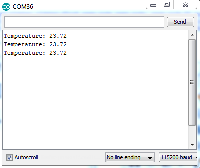
The new version of this code provides repeatable results within 0.2°C, while the first version can only provide repeatable results within 0.5°C. If all went fine, you should see the Serial Monitor window showing information similar with Figure 13
Measure Light Intensity with a Photo Resistor
A photo-resistor is a special type of resistor which change its value based on the ambient light intensity. Usually, these resistors have specified values for "complete dark" and "extreme light", and normally the datasheet presents a mapping function allowing to transform a resistance value into a luminous emittance value (measured in LUX).
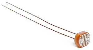
In this tutorial we discus about VT93N1 photo-resistor, fairly easy to use and with a low price of about 1EUR for one piece, EU postage included. Being a resistor, it can be mounted either way in a circuit. Figure 14 shows the pyhsical shape of a VT93N1 photo-resistor. In Table 4 are shown the most important characteristics of the VT93N1 sensor.
| Range | Accuracy | Resolution | Adaptation time | Operating voltage | Max. power dissipation |
|---|---|---|---|---|---|
| [12, 300]kΩ | ±20% | 1Ω | min. 5 seconds | [-60, 60]V | 80mW |
| Download datasheet | |||||
It is possible to measure a resistor, thus a photo-resistor too, by using various techniques such as:
- Use a constant current source, measure the dropout voltage over the resistor, then use Ohm's law to compute the resistance:
R = V / I, where R is the resistance in ohms we want to measure, V is the dropout voltage in volts across the resistor, and I is the applied constant current value in Amperes. - Use a voltage divider with another precision resistor, for which the resistance value is already known. Apply a known voltage across the end of the resistor network and measure the voltage drop across the resistor with the known value. The equation which applies is:
V_across_R2 = R2 * V_input / (R1 + R2). We solve this for R1, that is the resistance we are interested in:R1 = R2 * (V_input / V_across_R2 - 1). Therefore, if we know the applied voltage to the circuit, the value of the fixed R2 resistor, and we measure the voltage drop across R2, we can easily compute the value of R1, measured in ohms.
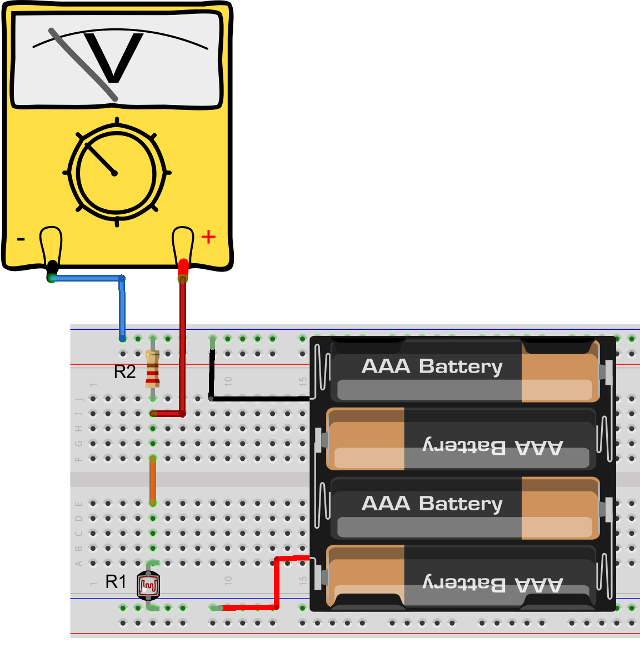
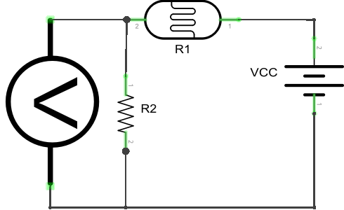
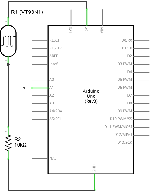
In our case, since we don't have a constant current source, but we can use a resistor of a known value, the second method is used, as shown in Figure 15, respectively Figure 16. However, we'll use the Arduino UNO ADC capabilities to replace the voltmeter, as we learned earlier in this tutorial.
Hardware Configuration
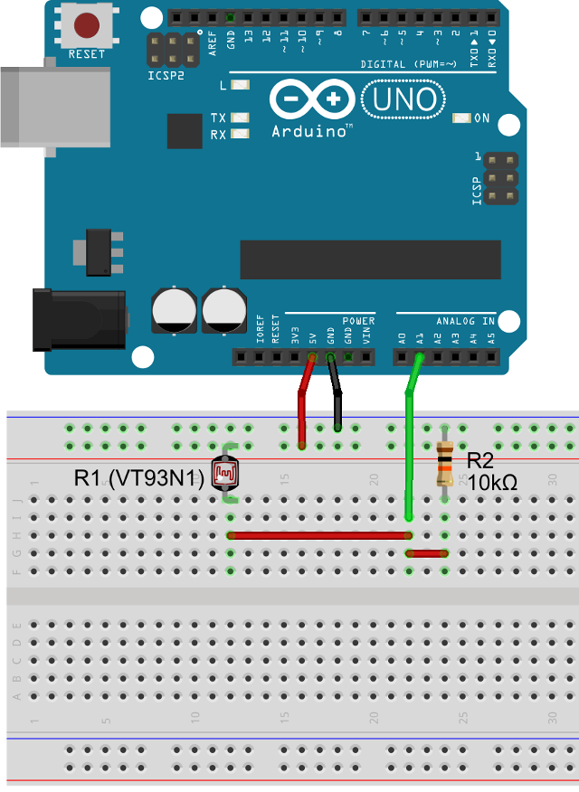
For being able to measure the luminous flux, we need to measure the resistance of the VT93N1 photo resistor, then use a formula to map this to the corresponding LUX value. In Figure 17 is shown how to connect the VT93N1 photo resistor to an Arduino UNO board, and for more details, in Figure 18 the circuit diagram is also shown.
Due to the relatively low accuracy of the VT93N1 sensor and also because of the high variations of light in a real environment, it is possible to obtain relatively high fluctuations, even if looks to be no change in the light, as perceived by the human eyes. This is relative, and for being able to characterize the performance of your sensor, a higher accuracy LUX-meter device may be required.
Without an initial calibration, using a high precision LUX-meter, the error factor may be as high as 20%. This can be reduced to about 5-10%, when using high precision resistors with a well known value, a good voltmeter for initial voltage drop measurements and a high precision LUX-meter. However, this is only needed if you'll need to use this sensor for sensitive projects. To detect if is getting dark in a room, so a light turns on automatically, or to check if some plants have enough light in their current location (plants can tolerate high light variations) this cheap sensor even without any initial calibration is sufficient.
Software Configuration
We deal with an analog devices, that point us in using an analog pin of our Arduino UNO board, e.g., pin A1 for this example.
#define VT93N1_PIN A1
As in all our examples, we use the Arduino serial monitor to show sensor data. In addition, the sensor datasheet tells us that at least 5 seconds are needed for having the sensor adapted to the environmental light, so a 5 seconds delay is used at startup.
void setup() {
  Serial.begin(115200);
  delay(5000);
}
Since the datasheet does not provide a mapping function to transform a resistance value into a LUX value, we'll need to use our friend Google, which soon provide us with an response. The formula we can use is: E = 341.64 / R^(10 / 9), where E is the luminous emittance in LUX, and R is the resistance in kΩ (kilo ohms).
void loop() {
  double vAcrossR2 = 0, r1 = 0, luxValue = 0,
         vInput = 5, r2 = 10000;

  // collect 10 samples and average to obtain stable value.
  for ( byte i = 0; i < 10; i++) {
    // read voltage from pin, in Volts
    vAcrossR2 += analogRead(VT93N1_PIN) * 0.00488;
  }
  vAcrossR2 = vAcrossR2 / 10.0;

  // calculate resistance r1 = 22 * (vInput / vAcrossR1 - 1)
  r1 = r2 * ( vInput / vAcrossR2 - 1);

  // convert resistance value to LUX value for this sensor based in formula:
  // E = 341.64 / R^(10 / 9), where R is measured in kOhm
  luxValue = 341.64 / pow( r1 / 1000.0, 10.0 / 9.0);

  Serial.print("LUX: ");
  Serial.println(luxValue);

  delay(5000);
}
There are a few points in the code that requires explanations:
- Computing the resistance is made as shown below in this tutorial, with respect to a voltage divider circuit, using the equation:
R1 = R2 * (V_input / V_across_R2 - 1). - Ten samples of ADC readings are taken, to improve the stability.
- The
powmethod is used to calculate the exponential value: its first argument is the base and the second is the exponent.
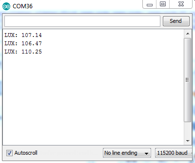
If all went fine, you should see the Serial Monitor window showing information similar with Figure 19.
Some Points of Attention
The examples from this tutorial show how to use the sensors with an Arduino UNO board. However, the same code and connections work with almost any other Arduino board. It is important to notice that some Arduino boards, such as Arduino DUE, use 3.3V as input (VCC = 3.3V). Therefore, you should use sensors that are able to receive power from a 3.3V source instead of 5V one. This is required for being able to directly connect sensor pins to Arduino pins without destroying your Arduino board.
There are cases when we really want or need to use a 3.3V an Adruino board with a 5V powered sensor, or a 5V Arduino board with a 3.3V sensor. The solution for this problem is to use voltage level converter. It is possible to build one by using small FETs (Field Effect Transistors) or by using voltage divider circuit (not the most recommended way, but still the cheapest and easiest) or you can simply buy a specially designed board which takes care of such tasks. In Figure 20 is shown such a ready to use small board that provides four I/O level converter pins from 3/3.3V to 5V and back. Such boards costs as less as 1-2€ per piece, postage in EU included (e.g., use eBay).

Another special attention has to be paid to the power supplyused for your project. Cheap ones comes usually with low regulation, that is, the maximum ±5% allowed tolerance is not really what we get, thus causing all kind of strange problems with your micro-controller, such as resets. This is even worst when using analog sensors, which are usually highly sensitive to voltage variation, and even a ±1% variation may reduce the accuracy to a few levels of magnitude. As a general advice, either use a high quality power source (that can be expensive for a DIY project!), or at least add a 0.1µF ceramic capacitor in parallel with a 100µF (or larger, up to 1000µF) electrolytic capacitor on the power supply line, before any other device in the circuit. This allows for high frequency (the small ceramic capacitor) and low frequency (the larger electrolytic capacitor) spikes filtering (at some level), thus improving the general behavior of the circuit.
Next Tutorial: Part 3 - WiFI Network Connection and Cloud Data Storage
In this tutorial we'll learn how to use an ESP8266 WiFi module (there are 13 or more different variations) to connect an Arduino based sensor node to network, and use free online services to store data for later analyze, or provide charts showing the evolution of the measured environment properties over time.
The ESP8266 WiFI module is a cheap way to empower a device very limited in resources, such as the Arduino UNO board, with a standard 802.11g/b/n WiFi network connection, and allow it to communicate (as a client) with another devices, or services, by using standard HTTP/HTTPS protocols, i.e., GET, POST and PUT methods. In addition, custom UDP based communication is also possible when using ESP8266 WiFi module and the right firmware.
Stay tuned, the release date is: before 10 May 2016.