
Game On: Intel® Edison with the Xadow Wearable Kit
Game On: Intel® Edison with the Xadow Wearable Kit
Get access to the new Intel® IoT Developer Kit, a complete hardware and software solution that allows developers to create exciting new solutions with the Intel® Galileo and Intel® Edison boards. Visit the Intel® Developer Zone for IoT.

Most people’s first view of the Intel® Edison module is installed on the Arduino* expansion board, which looks too large for mobile use. That is why many developers don’t think of Edison as functional in a compact or wearable device.
As you can see in the picture, the Intel® Edison module is quite small. But it's not so easy to use, because the pins for connecting peripherals are tiny: the Hirose connector on the Intel Edison board has 70 pins, while its length is just about 1 cm. One of the ways to solve this problem is by using the Xadow Wearable Kit for Intel® Edison provided by Seeed. This kit contains all the necessary adapters and small sensors to design a compact wearable device.
The kit includes small expansion boards with different features. All the boards are connected by a flexible flat cable (FCC). You can connect the boards in a daisy-chain to provide necessary features on your device.
This is what the kit includes:

Each of these components are described in the Wearable Kit Components section of this document.
-
- Battery.
- Xadow – Edison: the main connector to plug in the Intel® Edison board.
- Xadow – Edison Programmer: a module to connect Intel® Edison to PC via USB.
- Xadow – Edison SD: a module to connect an SD memory card.
- Xadow – OLED: 128x64 monochrome OLED display.
- Xadow – Buzzer.
- Xadow – Vibration Motor.
- Xadow – Q Touch Sensor: touch buttons.
- Xadow – NFC: NFC reader.
- NFC Tags – three NFC tags (one pictured).
- Xadow – 3Axis Accelerometer.
- Xadow – Barometer BMP 180: barometer and thermometer.
- Digital RGB LED Flexi-Strip: a strip with five controlled RGB LEDs.
- FFC cable package.
- Power cable (not pictured).
Introductory Notes
Before describing the process some peculiarities and problems and their solutions I discovered while working on this project should be noted. First, I strongly recommend updating board firmware.
To check the current version, use the following command:
configure_edison –version
At the time of writing, the current board firmware version is 159.
I also recommend updating all the installed libraries. You'll need an Internet connection for that.
opkg update
opkg upgrade
All code samples in this article are for Arduino* IDE. The developer of the Seeed kit doesn't provide samples for other IDEs.
I tried to use the board with Intel® XDK for IoT and С++, but couldn't make it work. One possible reason is that the board circuitry is different from that of the standard Arduino expansion board. There are also some problems with the I2C interface, and the operation of the accelerometer is not always stable. However, it worked properly in the game set, in which it was connected after the OLED display. I couldn't get the barometer/thermometer board to operate.
Sometimes the connection of the board to Arduino* IDE failed, or the compilation and transfer of a sketch did not work. In this case you should terminate the sketch running on the board:
systemctl stop clloader
After, clear the /sketch folder, and close all running Arduino* IDEs on the PC. Power off the Intel® Edison board (using shutdown now) and turn it on again by holding the PWR button until the LED goes on.
If you need the Edison board to run the sketch when powered on, you can create a file to run on boot: Create the folder /etc/init.d. In that folder create a file named automateSketch.sh containing the following:
#!/bin/sh
exec /sketch/sketch.elf /dev/ttyGS0 /dev/ttyGS0
After creating and saving automateSketch.sh, make the file executable:
chmod +x automateSketch.sh
Then add automateSketch.sh to the startup list:
update-rc.d automateSketch.sh defaults
Getting Started
You should have all the Intel Edison drivers installed on your PC. All interaction with the modules from this kit is carried out by means of Arduino* sketches, so you should install Arduino* IDE, if you haven't already. You can download it from www.arduino.cc.
To work with the board, you should connect the Xadow-Edison Programmer module. Please note that both USB ports should be plugged in: one of them supplies the power, and the other connects to Arduino* IDE. The switch on the board should be set to the "Device" position. Please select the Intel Edison board in your Arduino* IDE using Boards Manager.
After the Edison OS boots up (about 30 seconds), find the number of the virtual port in the Device Manager on your PC.

Select Intel® Edison Virtual Com Port (COM25) in the Arduino* IDE. You can use USB Serial Port (COM29) to connect to the console, e.g. via Putty.
Arduino* Libraries
Libraries are necessary to interact with the modules. You can download the libraries at github.com/Seeed-Studio/Xadow_Edison_Demos –as a single ZIP file. Most likely, you won't be able to install the whole package at once, so you'll have to add the folders with required libraries in the IDE menu.
Connecting Modules
Disconnect the power from Intel Edison before plugging in any modules to reduce the chance of damaging the components. If you try to hot-plug modules, the sketches stop loading properly.
All the modules are connected with flexible flat cable (FFC). The cables vary in length and width; the width of a cable should match the connector. All the cables are inserted with the blue side up, pins down. There are two types of connectors on the boards. The first type opens upwards, like a cover. Open the connector, put the cable lightly all the way in (about 3 mm), then close the connector.

The second type of connector is a sliding clamp, which is less convenient. You should pry it off at the sides and pull out by about 1 mm. Be careful, I accidentally broke one of the pins. Put in the cable as far as it can go (about 3 mm) with a little pressure. Then push in the connector with a little effort. The cables should stay firmly in the connectors.

All the modules have connectors on opposite ends. All the modules and the main board also have beveled corners on one side. You should connect all the boards in such a way that these bevels are on the same side. In the following picture you can see they are all on the left.

Wearable Kit Components
Each part in the kit, as described in the beginning of this document can be used to create many different kinds of wearable tech depending on how you combine them and program them.
Battery
The battery for this system is a standard 3.7 V, 500 mAh Li-Ion battery.

Xadow - Edison

This is the main board for connecting the Edison module, and it is slightly larger than the module itself. If you plug the Edison module into its socket, it will hold firmly, but for extra security you can attach it with screws from the Arduino* module.
The board has a connector for the battery, and four connectors for expansion boards on the sides. The upper connector is for Edison Programmer board, the side connectors are for sensor and actuator boards, and the bottom connector is for the SD card module.
There are two buttons, PWR and FW_RCVR. Press and hold PWR to turn the device on and off—hold for 9 seconds to power off, and for 2 seconds to power on.
A small green LED near the battery connector indicates the power status. If it is blinking, the power is supplied via USB. If it is steady, the battery is charging. If it is off, the battery is charged.
This board and the battery are all you need to make Edison work.

The functioning of this compact device made a great impression on me: this small board with a battery is a mini-PC with real Linux* OS, accessible over WiFi*.
Xadow - Edison Programmer

This is a board for PC connection. You can use it for debugging and supplying power from the PC. It contains two Micro USB connectors:
- The UART connector connects to a PC via a COM port and supplies power.
- The Device/Host connector operates the board from Arduino* IDE. There is a switch to select "Device" or "Host" mode. For Arduino*, select "Device.”
Xadow - Edison SD
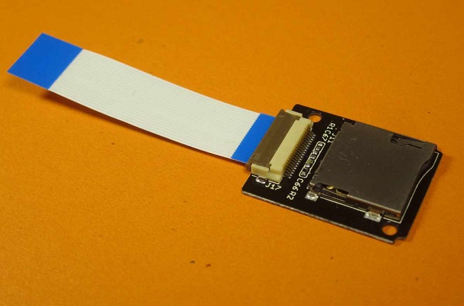
This board contains a connector to plug in an SD memory card. It is connected to the bottom socket on the main board with the widest cable.
You can find the SD card in the device directory in /dev/mmcblk1.
When mounting, follow the standard Linux procedure. Create an empty folder, e.g.:
mkdir /home/data
Then mount the card to this folder:
mount /dev/mmcblk1 /home/data
To mount the card automatically when Linux boots up, add the following string to the /etc/fstab file:
/dev/mmcblk1 /home/data auto auto 0 0
Xadow - OLED 12864
The display included in the kit is an 128x64 OLED display.

See the specifications at the Seeed website.
The display is connected via the I2C interface. The device address is 0x3C.
The following code is a screen display sample:
#include <Wire.h>
#include <SeeedOLED.h>

void setup()
 {
  Wire.begin();
  SeeedOled.init();  //initialze SEEED OLED display
  SeeedOled.clearDisplay();          //clear the screen and set start position to top left corner
  SeeedOled.setBrightness(255);
  SeeedOled.setNormalDisplay();      //Set display to normal mode (i.e non-inverse mode)
  SeeedOled.setPageMode();           //Set addressing mode to Page Mode
  SeeedOled.setTextXY(0,0);          //Set the cursor to Xth Page, Yth Column
  SeeedOled.putString("Xadow and Edison"); //Print the String

  SeeedOled.setTextXY(7,0);          //Set the cursor to Xth Page, Yth Column
  for(int k = 0; k < 128; k++)
  {
    SeeedOled.sendData(k);
  }
}

void loop() {
}
The screen contains 8 rows, 16 characters in each row, with a framerate of several frames per second.
We used the following functions:
init()– Initializes the Seeed OLED frame and sets the display to Normal mode.clearDisplay()– Clears the whole screen. Should be used before starting a fresh start or after scroll deactivation. This function also sets the cursor to top left corner.setBrightness(unsigned char Brightness)– Set the contrast ratio of OLED display. Brightness can be any number from 0 - 255.setNormalDisplay()– Configures the display to normal mode(non-inverse) mode.setPageMode()- Configures the display to page addressing mode.setTextXY(0,0)- Set the text's position (cursor) to Xth Page, Yth Column. X can be any number from 0 - 7. Y can be any number from 0 - 127.putString(cont char *string)- Print string to OLED display starting from current address-pointer set by setTextXY(X,Y).sendData(unsigned char Data)– send one byte to the screen.
Other functions and more information you can find at www.seeedstudio.com/wiki/OLED_Frame and in SeeedOLED.h file.
Xadow - Buzzer

The buzzer is connected to pins 11 and 13. You have to turn them on and off simultaneously. To make sound, you send 0 or 1 to both pins.
I've learned from experience that the simplest method is to preset one of the pins to 1 and then change the state of the other pin to make sound.
The following code is a sound output sample:
void buzzerInit()
{
    pinMode(11,OUTPUT);
    pinMode(13,OUTPUT);
}

void buzzerOn()
{
    digitalWrite(11,HIGH);
    digitalWrite(13,HIGH);
}

void buzzerOff()
{
    digitalWrite(11,LOW);
    digitalWrite(13,LOW);
}

void buzzerSignal(int t_ms)
{
    unsigned long cur = millis();
    while((millis()-cur) < t_ms )
    {
        buzzerOn();
        delayMicroseconds(150);
        buzzerOff();
        delayMicroseconds(150);
    }
}

void setup()
{
    buzzerInit();
    buzzerSignal(1000);
}

void loop()
{
}
As the playback is software-based, the sound is not very clear. It would be better to use pulse-width modulation. It is worth mentioning that a replica of this sketch that I made for Intel® XDK for IoT and С++ did not work – there was no sound.
Xadow - Vibration Motor

You can control the vibration motor in the same way as the buzzer: turned on and off via setting pins 10 and 11 to the same value. This sample code shows one method:
// Xadow - Vibro
void vibroInit()
{
    pinMode(11,OUTPUT);
    pinMode(10,OUTPUT);
}

void vibroOn()
{
    digitalWrite(11,HIGH);
    digitalWrite(10,HIGH);
}

void vibroOff()
{
    digitalWrite(11,LOW);
    digitalWrite(10,LOW);
}

void setup()
{
    vibroInit();
    vibroOn();
    delay(500);
    vibroOff();
}

void loop()
{
}
Just as with the buzzer, you need to control only one pin, after presetting 1 on the other pin.
Xadow - Q Touch Sensor

The board contains three touch buttons on the back side, and connects via I2C; the address is 0x1B.
The buttons are very sensitive. They sense touches even through several layers of paper or film, so you can cover the buttons with pictures.
Here is sample code, which returns the number of the button pressed:
#include <Wire.h>
#include "Seeed_QTouch.h"

void setup()
{
    Serial.begin(9600);
    Wire.begin();
}

void loop()
{
    int tn = QTouch.touchNum();

    if(tn>=0)
    {
        Serial.print("KEY");
        Serial.print(tn);
        Serial.println(" touched");
    }

    delay(10);
}
Xadow - NFC

The NFC reader supports I2C, SPI, and UART connections. The operating frequency is 13.56 MHz. It supports read and write operations, ISO14443 Type A and Type B protocols, and P2P. There is an antenna with connection wire. See more at http://www.seeedstudio.com/wiki/Xadow_-_NFC
The kit includes three empty writable NFC tags.
![]()
This module requires the NDEF, PN532, PN532_HSU, PN532_I2C, and PN532_SPI libraries. Install these libraries from the common Seeed library of samples.
To test the tags and the reader, you can use the sample program readTag in the NDEF library. It reads the data from the tag and displays it in the console.
The tags in the kit have serial numbers. As they are not yet formatted, they return the following output when queried:
Tag is not NDEF formatted.
NFC Tag - Mifare Classic
UID 6E A5 0B 01
In order to write some data to the tags, they need to be formatted with the FormatTag sample in the NDEF library.
To write data to a tag, you can use the WriteTag sample in the NDEF library.
This is a result of reading data from a tag:
NFC Tag - Mifare Classic
UID 5E B1 FB 01

NDEF Message 1 record, 28 bytes
  NDEF Record
    TNF 0x1 Well Known
    Type Length 0x1 1
    Payload Length 0x18 24
    Type 55  U
    Payload 00 49 6E 74 65 6C 20 45 64 69 73 6F 6E 20 77 69 74 68 20 58 61 64 6F 77  .Intel® Edison with Xadow
    Record is 28 bytes
Xadow - 3Axis Accelerometer

This is the three-axis acceleration sensor. The measured range is ±16 G. It is connected via I2C and the address is 0x53. The sensor is installed on the ADXL345 chip. To use it, install the DigitalAccelerometer_ADXL345 library from the kit.
There are four measurement ranges, with different precision rates and conversion ratios: ±2 g, ±4 g, ±8 g, ±16 g.
The chip datasheet can be found here: pdf1.alldatasheet.com/datasheet-pdf/view/254714/AD/ADXL345.html
The data are returned as 16-bit numbers. The library returns numbers as int variables, so you have to modify them as follows:
void correct(int &a)
{
 if( a > 32767 )
     a = -(65536 - a);
}
If you use the ±2g range, then the returned values should be divided by 256, per the datasheet. As I mentioned, I encountered some problems with the accelerometer. Sometimes it couldn't be detected, and the Linux console returned I2C errors. However, the operation was stable when I connected the screen to the main module, and then connected the accelerometer to the screen. Maybe this sensor doesn’t have termination resistors.
Xadow - Barometer BMP 180

This board contains a barometer and thermometer. The pressure measurement range is 300–1100 hPa (i.e., -500m to +9000m above sea level). It connects via I2C using the 0x77 address.
Unfortunately, I couldn't make it work, probably due to some errors in the I2C interface. Maybe it is the same problem as for accelerometer. I have tested other Xadow kit and it doesn’t work either.
Xadow - Breakout
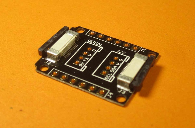
This is a board to connect standard sensors. It has the following pins: 3.3 V, SCL, SDA, TX0, GND, SCK, MOS1, MOS0, A5. There are also two pads for the connector to which standard "Seeed" modules can be plugged. One is marked as "Serial," the other "I2C." You can connect the LED strip.
Digital RGB LED Flexi-Strip

This is a strip with 5 RGB WS2812B LEDs. The LEDs are controlled through a single wire.
You need to solder them for proper connection, as illustrated in the next image. Use the Xadow-Breakout board.


The data are sent by software, so sometimes there are data transmission errors and the LEDs may randomly blink.
This is the "Running light" program:
#include <Wire.h>
#include "Seeed_ws2812.h"

#define SIG_PIN 12
#define LEN_NUM 5

WS2812 strip = WS2812(LEN_NUM, SIG_PIN);

void setup() {
  strip.begin();
  //Serial.begin(115200);
}

int pos = 0;

void loop() {
  strip.WS2812SetRGB(pos,255,0,0);
  strip.WS2812Send();
  delay(100);

  strip.WS2812SetRGB(pos,0,0,0);
  strip.WS2812Send();
  delay(100);

  pos = (pos+1)%LEN_NUM;
}
Creating a Game
I wanted to make something with this kit, and I got the idea for a game.
In this game, the LED strip is attached to the outer side of the game box. As the LEDs flash on and off, the player tilts the box 45 degrees in a direction depending on the LED color If the middle LED goes green, you should tilt the box forward (away from you). If the middle LED goes red, you should tilt the box to yourself. If the rightmost LED goes green, tilt the box to the right, but if this LED goes red, tilt the box to the left.
This game is designed not only to test reaction, but to make the player think before they act.

To create the game, you need the following components:
- Gyroscope
- OLED display
- LED strip
- Expansion module to connect the strip
- Button board
- Battery
First, I connected the Breakout board from the side of the battery connector, then the sensor buttons. On the other side, I connected the screen, then the gyroscope. I made the box by gluing together sheets of thick colored paper. Then I cut out an opening for the screen. I attached the button board under the screen; as you remember, button sensitivity is very high. On the front side, I drew the signs over the buttons.
All the boards are attached with clear tape over a layer of paper, to avoid damage.
![]()
The sketch starts automatically in Linux.
To start the game, hold the PWR button on the main module for about 9 seconds. To turn the game off, hold the same button for 3 seconds.
When the game is launched, a menu appears, and in this menu you can start a game (press button A) or display Help (press button B). To close the Help screen, press the arrow button.

The game consists of five rounds. In each round a random LED is lit, and you have to tilt the box in a certain direction. If you did it right, the screen will display "You Win!" If you fail or the time runs out, the screen will display "You Lose!"
You may see example video https://www.youtube.com/watch?v=1Tjff7wDPIQ
All the game code is in one file. I tried to make it as simple as possible, so that it is easy to analyze.
Game Sketch Code
#include <Wire.h>
#include <Seeed_ws2812.h>
#include <SeeedOLED.h>
#include <Seeed_QTouch.h>
#include <ADXL345.h>

// game state
const int stateMenu = 1;
const int stateCount = 3;
const int stateHelp = 4;

// buttons
const int keyBack = 0;
const int keyA = 1;
const int keyB = 2;

// LED strip
const int ledSigPin =  12;
const int numLed = 5;

// answers
const int answerLeft = 1;
const int answerRight = 2;
const int answerUp = 3;
const int answerDown = 4;

const int colorGreen = 1;
const int colorRed = 2;

const int numLevels = 6;
const int answerID = 5;

const int angleScale = 100;
const int angleReact = 100;//tangent of actuating angle * angleScale

int numWins;// number of wins
int numLosts;// number of losses
int gameState;// game state

const int numSets = 5;// number of rounds in a game

// level coding
int levels[numLevels][numLed+1] = {  {colorGreen,0,0,0,0,answerLeft},
                             {colorRed,0,0,0,0,answerRight},
                             {0,0,0,0,colorGreen,answerRight},
                             {0,0,0,0,colorRed,answerLeft},
                             {0,0,colorGreen,0,0,answerUp},
                             {0,0,colorRed,0,0,answerRight}};
// correct answer
int rightAnswer;

WS2812 strip = WS2812(numLed, ledSigPin);
ADXL345 adxl;

// current game level
int gameLevel;

// initialization of accelerometer
void initAccel()
{
  adxl.powerOn();

  //set activity/ inactivity thresholds (0-255)s
  adxl.setActivityThreshold(75); //62.5mg per increment
  adxl.setInactivityThreshold(75); //62.5mg per increment
  adxl.setTimeInactivity(10); // how many seconds of no activity is inactive?

  //look of activity movement on this axes - 1 == on; 0 == off
  adxl.setActivityX(1);
  adxl.setActivityY(1);
  adxl.setActivityZ(1);

  //look of inactivity movement on this axes - 1 == on; 0 == off
  adxl.setInactivityX(1);
  adxl.setInactivityY(1);
  adxl.setInactivityZ(1);

  //look of tap movement on this axes - 1 == on; 0 == off
  adxl.setTapDetectionOnX(0);
  adxl.setTapDetectionOnY(0);
  adxl.setTapDetectionOnZ(1);

  //set values for what is a tap, and what is a double tap (0-255)
  adxl.setTapThreshold(50); //62.5mg per increment
  adxl.setTapDuration(15); //625us per increment
  adxl.setDoubleTapLatency(80); //1.25ms per increment
  adxl.setDoubleTapWindow(200); //1.25ms per increment

  //set values for what is considered freefall (0-255)
  adxl.setFreeFallThreshold(7); //(5 - 9) recommended - 62.5mg per increment
  adxl.setFreeFallDuration(45); //(20 - 70) recommended - 5ms per increment

  //setting all interrupts to take place on int pin 1
  //I had issues with int pin 2, was unable to reset it
  adxl.setInterruptMapping( ADXL345_INT_SINGLE_TAP_BIT,   ADXL345_INT1_PIN );
  adxl.setInterruptMapping( ADXL345_INT_DOUBLE_TAP_BIT,   ADXL345_INT1_PIN );
  adxl.setInterruptMapping( ADXL345_INT_FREE_FALL_BIT,    ADXL345_INT1_PIN );
  adxl.setInterruptMapping( ADXL345_INT_ACTIVITY_BIT,     ADXL345_INT1_PIN );
  adxl.setInterruptMapping( ADXL345_INT_INACTIVITY_BIT,   ADXL345_INT1_PIN );

  //register interrupt actions - 1 == on; 0 == off
  adxl.setInterrupt( ADXL345_INT_SINGLE_TAP_BIT, 1);
  adxl.setInterrupt( ADXL345_INT_DOUBLE_TAP_BIT, 1);
  adxl.setInterrupt( ADXL345_INT_FREE_FALL_BIT,  1);
  adxl.setInterrupt( ADXL345_INT_ACTIVITY_BIT,   1);
  adxl.setInterrupt( ADXL345_INT_INACTIVITY_BIT, 1);
}

void initGame()
{
  SeeedOled.clearDisplay();
  SeeedOled.setNormalDisplay();
  SeeedOled.setPageMode();

  switchToMenu();
}

void setup()
{
    strip.begin();
    SeeedOled.init();
    initAccel();
    initGame();
}

void cleanLED()
{
  for( int led = 0; led < numLed; led++ )
      strip.WS2812SetRGB(led,0,0,0);
}

void updateLED()
{
  strip.WS2812Send();
}

void drawMenu()
{
  SeeedOled.clearDisplay();
  SeeedOled.setTextXY(0,2);
  SeeedOled.putString("Edison Game");

  SeeedOled.setTextXY(2,1);
  SeeedOled.putString("A - Start");

  SeeedOled.setTextXY(4,1);
  SeeedOled.putString("B - Help");
}

void drawHelp()
{
  SeeedOled.clearDisplay();

  char *messages[] = {    "Center green -",
    "tilt forward." ,
    "Center red -" ,
    "tilt backward.",
    "Green edge -" ,
    "tilt same side." ,
    "Red edge - tilt",
    "other side."
 };

   for( int k = 0; k < 8; k++ )
   {
      SeeedOled.setTextXY(k,0);
      SeeedOled.putString(messages[k]);
   }
}

void makeNewLevel()
{
    gameLevel = rand() % numLevels;
    rightAnswer = levels[gameLevel][answerID];
}

void showGameStart()
{
  SeeedOled.clearDisplay();
  SeeedOled.setTextXY(0,0);
  SeeedOled.putString("Press Start");
}

int getKeys()
{
    int tn = QTouch.touchNum();
    return tn;
}

int haveTime = 20;

void showGameLevel()
{
  for( int k = 0; k < numLed; k++ )
  {
     int color = levels[gameLevel][k];
     switch(color)
     {
         case colorRed  : strip.WS2812SetRGB(k,255,0,0); break;
         case colorGreen: strip.WS2812SetRGB(k,0,255,0); break;
         default        : strip.WS2812SetRGB(k,0,0,0);
     }
  }

  updateLED();
}

void switchToSets()
{
  numWins = 0;
  numLosts = 0;
  switchToPlay();
}

//------------------------------------

void switchToPlay()
{
  cleanLED();
  updateLED();

  SeeedOled.clearDisplay();
  SeeedOled.setTextXY(3,3);
  SeeedOled.putString("Get ready!");

  int waitTime = 2000 + (rand()%4)*500;

  delay(waitTime);

  makeNewLevel();

  SeeedOled.setTextXY(3,3);
  SeeedOled.putString("          ");

  haveTime = 100;
  gameState = stateCount;
}

void doPlay()
{
  if( haveTime >= 0 )
  {
    SeeedOled.setTextXY(3,1);
    char str[100];
    sprintf(str,"-- TILT NOW --");
    SeeedOled.putString(str);

    SeeedOled.setTextXY(5,6);
    sprintf(str,"%d  ",haveTime);
    SeeedOled.putString(str);

    showGameLevel();

    int answerID = getAnswerID();

    haveTime--;

    if( answerID !=0 || haveTime < 0)
    {
      char *message;
      if( answerID != rightAnswer || haveTime < 0)
      {
        numLosts++;
        message = "You lose!";
      }
      else
      {
        numWins++;
        message = "You win!";
      }

      cleanLED();
      updateLED();

      SeeedOled.clearDisplay();
      SeeedOled.setTextXY(3,4);
      SeeedOled.putString(message);

      delay(1000);

      if( numWins + numLosts == numSets )
      {
        switchToMenu();
      }
      else
      {
        switchToPlay();
      }
    }
  }
}

//-----------------------

void switchToHelp()
{
    drawHelp();
    gameState = stateHelp;

    cleanLED();
    updateLED();
}

void doHelp()
{
  cleanLED();
  updateLED();

  int key = getKeys();

  if( key == keyBack )
      switchToMenu();
}

//-----------------------
void switchToMenu()
{
  drawMenu();
  gameState = stateMenu;

  cleanLED();
  updateLED();
}

void doMenu()
{
  int key = getKeys();

  if( key == keyA )
      switchToSets();

    if( key == keyB )
      switchToHelp();
}
//-----------------------

void correct(int &a)
{
 if( a > 32767 )
     a = -(65536 - a);
}

int  getAnswerID()
{
  int x,y,z;
  adxl.readXYZ(&x, &y, &z);

  correct(x);
  correct(y);
  correct(z);

  int v1 = angleReact;
  if( z != 0 )
      v1 = y*angleScale/z;

  if( v1 > angleReact )
    return answerRight;

  if( v1 < -angleReact )
    return answerLeft;

  int v2 = angleReact;

  if( z != 0 )
      v2 = x*angleScale/z;

  if( v2 > angleReact )
    return answerUp;

  if( v2 < -angleReact )
    return answerDown;

    return 0;
}

void gameStep()
{
  switch(gameState)
  {
    case stateCount: doPlay();break;
    case stateMenu:  doMenu();break;
    case stateHelp:  doHelp();break;
  }
}

void loop()
{
    gameStep();
    delay(10);
}
About the Author
Valery Mosyagin is official Intel Software Innovator. He lives in Russia, Nizhny Novgorod. He has a Master’s Degree in Mathematics and Computer Science. He worked at Intel for 6 years in OpenCV team, then moved to Japan where he worked for Brain Research Institute developing software for biological experiments, later – software for network traffic analysis and radio coverage and propagation software. For a long time he teaches programming courses for children. He has a wide area of interests: virtual reality, game development, microcontrollers, IoT.