
Intel® Edison Board User Guide
Steps for setting up various components of your Intel® Edison board, including steps to flash your board's firmware, create a serial connection with your board, and connect your board to a Wi-Fi network.
Get access to the new Intel® IoT Developer Kit, a complete hardware and software solution that allows developers to create exciting new solutions with the Intel® Galileo and Intel® Edison boards. Visit the Intel® Developer Zone for IoT.
This reference guide contains steps for setting up various components of your Intel® Edison board, including steps to flash your board's firmware, create a serial connection with your board, and connect your board to a Wi-Fi* network.
Assembling and connecting your board
This section contains steps to set up your Intel® Edison board and connect it to your computer. Steps for your board may vary depending on the breakout board you have purchased.
For a guide to the various USB ports on the Arduino expansion board, see Connectors on the Intel® Edison board.
Assembling the Intel® Edison board with the Arduino expansion board
In this guide, you’ll set up the Intel® Edison module with an Arduino* expansion board.
Requirements
- Intel® Edison module
- Arduino expansion board
- 2 Micro B to Type A USB cables
- A direct current (DC) power supply. Your power supply should be rated as follows:
- 7-15V DC
- At least 1500mA
- The center/inner pin should be the positive pole of the power supply
We suggest an EMSA120150 or similar supply:
Set up your board
This section contains steps to attach your Intel® Edison module to your expansion board. A video of these steps is also available.
- Place the Intel® Edison module within the white outline on your expansion board, lining up the holes on the module with the screws on the expansion board.

- Press down on the module just below the words What will you make? until you feel a snap. When you turn the attached module and expansion board on their side, both pieces should fit evenly and sit in parallel with each other.

- Use the two hex nuts (included in the package) to secure the module to the expansion board.

- Insert a screw in the corner hole and attach the plastic spacer.

- Repeat for the other three corner spacers.

Connect the board to your system
This section contains steps to connect your Intel® Edison board to your computer. A video of these steps is also available.
- Plug in the power supply.
Note: If you do not have a DC power supply, you can still power the board through a USB port. Powering your board in this fashion may result in unpredictable behavior from your board, especially when using Wi-Fi* or driving motors. See the Powering your board over USB section for details.
- A green LED should light up on the expansion board. If it doesn't, check your connection.

- Find the microswitch in between the USB ports on the expansion board. Switch the microswitch down towards the micro-USB ports, if it isn't already.

- Plug in one of the micro-USB cables to the middle USB connector on the expansion board.

- Plug in the other end of the USB cable to your computer.

How do you know when the board is ready?
You will know that your board is fully initialized when your computer mounts a new drive (much like inserting a SD card into your computer). If you do not see a new drive, or the LED light (DS1 on the Arduino expansion board) is occasionally turning on and off, check the connection of your power supply.

- Plug in your second USB cable to the edge USB connector on the board.

- Plug the other end of the USB cable in to your computer.
Your board is now set up and connected.
Assembling the Intel® Edison board with the Intel® Edison mini breakout board
In this guide, you’ll set up the Intel® Edison module with an Intel® Edison mini breakout board.
Requirements
- Intel® Edison module
- Intel® Edison mini breakout board
- 2 Micro B to Type A USB cables

Note that the breakout board has two micro USB ports:
- The top port is used to create a terminal connection by serial over USB only.
- The bottom port is for power and USB communication.
For details, see the Intel® Edison Breakout Board Hardware Guide (PDF).
Assemble your board
At the end of this section, you should have an assembled Intel® Edison board.
- Place the Intel® Edison module on the breakout board, lining up the holes on the module with the screws on the breakout board. Press down on the module at the upper left corner and just below the words "What will you make?" until you feel it click into place.

- Use the two hex nuts to secure the module to the expansion board. Hand-tighten the hex nuts onto the two screws that protrude through the module.

- Plug in one of the micro-USB cables to the bottom USB connector on the expansion board. Plug in the other end of the USB cable to your computer. A green light should light up on the expansion board. If it doesn’t, check your connection.

- Wait a moment for the board to boot up. You will know that the board is fully initialized when your computer mounts a new drive (much like inserting a SD card into your computer).
- Plug in your second USB cable to the top USB connector on the board.
Note: If you do not see a new drive, it is likely that the board isn’t getting enough power from the USB port. Plug in your laptop’s AC adapter (if you are connecting the board to a laptop), try a different USB port on your computer, or try using a USB hub that has its own power supply.

Your board is now set up and connected.
Connectors on the Intel® Edison board
The Intel® Edison board provides a wide range of functionality for communicating with your board, uploading your code, updating the board firmware, and more. Refer to the image below for an overview of the various connectors on your board and what each is used for.

- Barrel connector for the external power supply: This connector is used for powering your board with an external power supply. For steps, see Powering your board.
- Standard USB port: This port is for regular connections of USB peripherals, such as mice, keyboards, and more. For steps, see Attaching USB peripherals to your board.
- Microswitch: You can switch between USB host mode and USB device mode using the microswitch.
- Device mode: In device mode, you can use your board as a computer peripheral using a micro-USB cable. In device mode, you can program the board over USB, mount the onboard flash memory like a disk drive, and more. For steps to connect the board as a computer peripheral, see Programming, powering, and writing to the onboard flash memory.
- Host mode: In host mode, you can plug USB peripherals with a standard-sized USB cable (such as mice, keyboards, and the like) in to the board. For steps, see Attaching USB peripherals to your board.
- Middle USB port (Micro A type): This port is used for the following:
- Power through USB Ethernet over USB
- Uploading Arduino sketches
- Updating the firmware by using the board as a storage device, like a flash drive
For steps, see Programming, powering, and writing to the onboard flash memory.
- Edge port (Micro A Type): This port is used to create a terminal connection by serial over USB only. For steps, see Establishing serial communications with your board.
For steps to connect to your board and access the functionality described above, see the appropriate section:
- Programming, powering, and writing to the onboard flash memory
- Establishing serial communications with your board
- Attaching USB peripherals to your board
- Powering your board
Programming, powering, and writing to the onboard flash memory
You can use the middle USB port on the board for the following:
- 5V power
- Programming your board using the Arduino IDE
- Programming your board using the Intel® XDK IoT Edition or Eclipse* IDE included in the Intel® IoT Developer Kit via Ethernet over USB (not Wi-Fi*)
- Writing to the onboard flash memory from your computer
When powering your board using the micro-USB port, keep in mind the following:
- Certain USB ports on your system might not be able to provide enough power to the board. This will ultimately result in some very unpredictable behavior from the board, especially when using Wi-Fi* or driving motors. To avoid this behavior, power your board using an external power supply.
- If you are connecting your board to a laptop, be sure to plug in your laptop's power supply to help ensure that your board has enough power.
- Find the microswitch in between the USB ports on the expansion board. Switch the microswitch down towards the micro-USB ports.
- Plug in a micro-USB cable to the middle USB connector on the expansion board.
- Plug the other end of the USB cable in to your computer.
- A green LED should light up on the expansion board. If it doesn't, check your connection.
- Wait one minute for the board to finish booting up.
How do you know when the board is ready?
You know that the board is fully initialized when your computer mounts a new drive (much like inserting a SD card into your computer). The Intel® Edison board needs approximately one minute to go through the entire Linux* startup process. There is no onboard LED to indicate whether or not the board is fully initialized; however, you can watch the full bootup sequence if you are connected to the board in a serial communication session. For steps to create a serial communication session with your board, see Setting up a serial terminal.
Establishing serial communications with your board
You can send serial commands to your board via Terminal or PuTTY using the edge micro-USB port. You can use these commands to flash firmware, configure Wi-Fi settings, or identify the board's IP address.
- Power your board by doing one of the following:
- With an external power supply (recommended): Plug the external power supply in to the barrel connector on the board.
- With the middle USB port: Plug a micro-USB cable in to the middle USB port on the board. Plug the other end in to your computer.
- Plug a micro-USB cable in to the edge micro-USB port on the expansion board.

- Plug the other end of the USB cable in to your computer.
Your board is now connected. For steps to create a serial communication session with your board, see Setting up a serial terminal. For steps to flash your firmware, see Flashing the firmware.
Once your board is online and has an addressable IP address, you may find it more convenient to SSH into your board to run Linux commands. In this case, you will not need the micro-USB serial cable on a regular basis.
Attaching USB peripherals to your board
Use the standard-sized USB port in USB host mode to allow the Intel® Edison board to accept USB peripherals, such as mice, keyboards, and more.
- Find the microswitch in between the USB ports on the expansion board. Switch the microswitch up towards the standard-sized USB port.

- Plug in the DC power supply to the barrel connector. The USB host mode requires the use of an external power adapter.
- Plug a USB peripheral with a standard-sized USB connector in to the standard-size USB port above the microswitch on the expansion board.

Powering your board over USB
To ensure that you have access to more power-intensive features such as Wi-Fi, a servo motor, or an Arduino shield, use an external direct current (DC) power supply) to power your board. An external power supply is the preferred way of powering the Intel® Edison board. However, you can power your board over USB if you do not have an external power supply. For details, see Programming, powering, and writing to the onboard flash memory.
Requirements
Your power supply should be rated as follows:
- 7-15V DC
- At least 1500mA
- The center/inner pin should be the positive pole of the power supply
We suggest an EMSA120150 or similar supply:
- Plug in the DC power supply to the barrel connector on your board.
- A green LED should light up on the expansion board. If it doesn't, check your connection.
-
Wait one minute for the board to finish booting up.
Installing drivers, software, libraries, and more
This section contains steps to install the drivers required to connect to your Intel® Edison board, the development software (such as Eclipse or the Intel® XDK IoT Edition) needed to program your board, and more.
If your system has 64-bit Windows* or Mac* OS X*, you can use a single integrated installer to install any required drivers, update your board's firmware, and install your choice of IDE at the same time. For links, see Windows* (64-bit) or Mac* OS X*.
See the appropriate link below:
Note: If your system has Mac* OS X* or Linux*, the appropriate FTDI drivers should already be installed. If they are not, install them from the FTDI page: http://www.ftdichip.com/Drivers/D2XX.htm
- Installing drivers for your board on a system with Windows*
- Installing your integrated development environment (IDEs)
- Updating the MRAA I/O and UPM sensor libraries
- Installing and managing board packages using OPKG
Installing drivers, updating firmware, and installing IDEs using the installers
Windows* (64-bit)
Use the Windows 64-bit Integrated Installer, which combines installing the FTDI and USB drivers, updating firmware and installing your choice of IDE. To access the features in the most current Intel® IoT Developer Kit release, always download the latest version of the integrated installer for your system.
As of the new release of Intel® IoT Developer Kit v1.5 on July 1, 2015: If you have previously set up your Intel® Edison board using the installer, you may be prompted to update the Intel® XDK IoT Edition to the latest version the next time you run it. Be sure to choose Download Now to take advantage of all the latest features from Intel for this release.
End-user license
Third-party program use
Mac* OS X*
Use the Mac OS X Integrated Installer, which combines updating firmware and installing your choice of IDE. To access the features in the most current Intel® IoT Developer Kit release, always download the latest version of the integrated installer for your system.
End-user license
Third-party program use
Installing drivers for your board on a system with Windows*
This guide contains steps to manually install drivers for your Intel® Edison board on a system with Windows*.
If your system has 64-bit Windows, you can run the Windows 64-bit integrated installer instead of installing the drivers manually. This installs the necessary drivers, updates your board's firmware, and installs your chosen IDEs. To access the features in the most current Intel® IoT Developer Kit release, always download the latest version of the integrated installer for your system. After the installer finishes, be sure to return to this book to set up serial terminal and network connections.
The Intel® Edison board drivers for Windows include several USB drivers in one installer package. These drivers enable important features, such as:
- Composite Device Class (CDC) for programming the board via the Arduino IDE
- Remote Network Driver Interface Spec (RNDIS) for Ethernet over USB
- Device Firmware Upgrade (DFU) for updating firmware on devices
Requirements
- You have assembled your board and connected it to your system. For steps, see Assembling and connecting your board.
- After connecting your board, you should see a drive called Edison show up in Windows Explorer. If you don’t, check that your board is properly powered on and connected via USB.
Install USB drivers
- Download the USB driver installer for the Intel® Edison board and run it.
- Click Next.

- Click I Agree.

- Click Next.

- Click Install.

- Click OK.

- Click Finish.

- Unplug the micro USB cable from the middle micro USB port, then plug it back in.

Install FTDI drivers
- Download the Windows setup executable from the following location: http://www.ftdichip.com/Drivers/D2XX.htm
- Right-click the file and select Run as administrator.

- Follow the on-screen instructions to install the drivers, then reboot your system.
- Navigate to the Device Manager and check for an entry called USB Serial Port (not Intel Edison Virtual Com Port). Make a note of the COM#, as highlighted below; you'll need this to create a serial communication session with your board.

Installing your integrated development environment (IDEs)
This section contains steps to install an integrated development environment (IDE) for your Intel® Edison board.
Which programming language will you use?
The IDE you use to program your board depends on the programming language you want to develop in. The choices are:
-
Arduino*: Arduino is an easy-to-learn, open source C++ based programming environment. It's convenient for quickly adding sensors since there is a lot of available sensor code out there. Since the Intel® Edison and Intel® Galileo boards are Arduino-pin compatible, there are also plenty of shields to choose from. The Arduino IDE is the application of choice for programming with Arduino. For steps to install the Arduino IDE, see Installing the Arduino IDE.
-
JavaScript* and Node.js*: These languages are great for creating web interfaces and also work well in cloud connectivity and getting devices talking to one another. We provide the Intel® XDK IoT Edition to program in JavaScript and Node.js. It comes with easy-to-use project templates to jumpstart your IoT projects. For steps to install the Intel XDK IoT Edition, see Installing the Intel® XDK IoT Edition.
-
C++: Alternatively, using C++ tends to be very powerful, giving you full control of the system while simultaneously taking advantage of a lot of available libraries. The Intel® IoT Developer Kit version of Eclipse*, which is downloadable, comes with a built-in capability to easily integrate sensors from our GitHub library. For steps to install Eclipse, see Installing the Eclipse* IDE.
Updating the MRAA I/O and UPM sensor libraries
You can check the version of the MRAA and UPM libraries installed on your board and update them to the latest versions available:
-
The MRAA I/O library (or libmraa) is a low-level library that offers a translation from the general purpose input/output (GPIO) interfaces to the pins available on the Intel® Galileo or Intel® Edison boards. MRAA makes it easier for developers and sensor manufacturers to map their sensors and actuators on top of supported hardware and to allow control of low-level communication protocol by high-level languages and constructs.
-
The UPM sensor library (or libupm) is a repository of sensor representations, written in C++ and utilizing MRAA. UPM is a high-level repository for sensors that use the MRAA library. Each sensor links to libmraa and is not meant to be interlinked, although some groups of sensors may be. Each sensor contains a header that allows you to interface with it.
The latest versions of MRAA and UPM can be found at their respective GitHub pages:
Updating the MRAA and UPM libraries
- Establish a serial communication session with your board.
- To ensure that you have the latest versions of the MRAA and UPM libraries, enter the following commands:
echo "src mraa-upm http://iotdk.intel.com/repos/1.1/intelgalactic" > /etc/opkg/mraa-upm.conf


opkg update - Enter the following commands to install the MRAA and UPM libraries:
opkg install libmraa0


	opkg install upm
Checking the version of the MRAA and UPM libraries installed on your board
- Establish a serial communication session with your board.
- To check the version number of the MRAA library installed on your board, enter the following command:
opkg info libmraa0 - To check the version number of the UPM library installed on your board, enter the following command:
opkg info upm
In the example image below, the version numbers are indicated with the red arrows.

Installing and managing board packages using OPKG
The OPKG utility is a lightweight package manager used to download and install OpenWrt packages from local package repositories or ones located on the Internet. It is possible to use OPKG to update your board packages as will be discussed later.
Package Manipulation
| update | Update list of available packages. This simply retrieves a file like this one: example, for your OpenWrt installation and stores it on your RAM partition under /tmp/opkg-lists/snapshots. Currently this occupies about 1,3 MiB of space. OPKG needs the content of this file in order to install or upgrade packages or to print info about them. And the content of the file needs to represent the current available packages in the repository. You can safely delete this file anytime to free up some RAM, just don't forget to fetch a new one, before trying to install a package. |
upgrade <pkgs> |
Upgrade packages. A list of upgradeable packages can be obtained with the opkg list-upgradable command. To upgrade a group of packages, run opkg upgrade packagename1 packagename2. Upgrading packages is generally not recommended for most users, because a typical OpenWrt system stores the base system in a read-only SquashFS partition. And while the upgrade process works just fine, it uses far more space than a default installation as the base packages are duplicated in the base SquashFS partition and the user JFFS2 partition. Thus, instead of upgrading, reflashing OpenWrt with a newer firmware image is recommended. Of course, upgrading packages installed afterwards does not have this drawback. Keep in mind though that for OpenWrt releases upgrading is for the most part not possible, since there is nothing to upgrade without changing the package repository. This is because the package repositories for OpenWrt's releases are generally not updated. However, the package repository in the trunk snapshots are updated by the build bots to new versions very often, as this is where the packages are updated, like the OpenWrt builds themselves. Note however that for kernel packages updating can be a risky business as it may brick the device if the trunk build kernel is incompatible with the new upgraded kernel package. You should therefore only upgrade non-kernel packages. |
install <pkgs|FQDN> |
Install package(s) Examples: opkg install hiawatha opkg install http://downloads.openwrt.org/snapshots/trunk/ar71xx/packages/hiawatha_7.7-2_ar71xx.ipk opkg install /tmp/hiawatha_7.7-2_ar71xx.ipk |
configure <pkgs> |
Configure unpacked package(s) |
remove <pkgs|globp> |
Remove package(s) |
flag <pkgs> <flag> |
Flag one or multiple package(s). Only one flag per invocation is allowed. Available flags: hold • noprune • user • ok • installed • unpacked |
Various options for the OPKG utility can be found at http://wiki.openwrt.org/doc/techref/opkg.
To install a package run the following commands. List of available packages is lost upon reboot, so make sure to update the list before trying to install a package.
opkg update opkg install <package>
To search:
opkg listwill display onlyPackage name — Version — Descriptionopkg infowill display all available information
Configuration
Adjust Repositories
The only configuration file is /etc/opkg.conf. It could look like this:
src/gz snapshots http://downloads.openwrt.org/snapshots/trunk/ar71xx/packages dest root / dest ram /tmp lists_dir ext /var/opkg-lists option overlay_root /overlay
It is possible to add other src locations to find package info to update. Modification of the opkg.conf will allow for multiple destinations.
Installation Destinations
The format of destination lines is simply the keyword dest, followed by a name for this destination (this can be anything), followed by a filesystem location. Any destination that has been thus configured can then be specified on the opkg command line like this:
opkg install somepackage -d destination_name
Flashing your firmware
This section contains steps to update (flash) the firmware on your Intel® Edison board using Flash Tool Lite. The firmware is your board's operating system, and also allows for use of Wi-Fi*, Bluetooth*, analog and digital controls, and other functions. It's important to keep your firmware up-to-date to ensure the best stability and performance for your board.
While flashing your firmware is not required to being programming your board, firmware updates contain vital features, such as the commands required to connect your board to a wireless network.
The recommended way to flash your firmware is using Flash Tool Lite, a GUI-based tool that simplifies the process. However, if you encounter errors, you can also flash the firmware using a manual process, or use the Update feature in Access Point (AP) mode.
- Using Flash Tool Lite (recommended)
- Flashing your firmware manually
- Getting started with Access Point (AP) Mode for the Intel® Edison board
Using Flash Tool Lite
This section contains steps to update (flash) the firmware on your Intel® Edison board using Flash Tool Lite. The firmware is your board's operating system, and also allows for use of Wi-Fi*, Bluetooth*, analog and digital controls, and other functions. It's important to keep your firmware up-to-date to ensure the best stability and performance for your board.
While flashing your firmware is not required to being programming your board, firmware updates contain vital features, such as the commands required to connect your board to a wireless network.
Requirements
- You have assembled your board and connected it to your system. For steps, see Assembling and connecting your board.
- You have installed any required drivers (for a system with Windows*). If you ran the installer for 64-bit Windows while setting up your board, your drivers are already installed.
- Your computer should have an operating system supported by Flash Tool Lite. Flash Tool Lite is supported for the following:
- Microsoft Windows* XP (32-bit)
- Microsoft Windows* 7 (32/64-bit)
- Microsoft Windows* 8 (32/64-bit)
- Microsoft Windows* 8.1 (32/64-bit)
- Ubuntu* 12.04 LTS 64-bit
- Mac* 10.9.5 64-bit
- Once you have connected your board, you should see a drive called Edison show up in Windows Explorer. Remember this drive letter (in this example it is D:) for later use.

Installing Flash Tool Lite
Flash Tool Lite is the preferred method of flashing your board's firmware. This GUI-based tool makes it much easier to manage firmware and other updates. It is possible to customize the installation and include packages with the firmware update. Flash Tool Lite doesn't require you to use a command line interface, but command line is available if desired. Currently, Flash Tool Lite is used to flash the firmware on Intel® Edison boards, but will expand to other IoT products in the future.
Before you use Flash Tool Lite, you must install it. The following sections contain steps to install Flash Tool Lite:
Note: If you run into errors while flashing your firmware, you can still flash your board manually. For steps, see Flashing the firmware manually.
Installing Flash Tool Lite on Windows*
This section contains steps to install Flash Tool Lite to update (flash) the firmware on your Intel® Edison board. The firmware is your board's operating system, and also allows for use of Wi-Fi*, Bluetooth*, analog and digital controls, and other functions. While installing and flashing your board is not necessarily required to begin programming your board, it's important to keep your firmware up-to-date to ensure the best stability and performance for your board. Flashing your firmware also gives you access to vital features, like the ability to connect your board to a wireless network.
For an introduction to flashing your firmware, see Flashing your board's firmware.
Requirements
- You have assembled your board and connected it to your system. For steps, see Assembling and connecting your board.
- You have installed any required drivers (for a system with Windows*). If you ran the installer for 64-bit Windows while setting up your board, your drivers are already installed.
Remove old images
- Open a new command window by clicking Start. Type
cmdand press Enter.
- Type the drive letter of the Intel® Edison board, which you noted earlier in the installation process. Press Enter.

- Enter the command:
del *
At the prompt, typeyand press Enter.
- All files should now be removed. To confirm, type
dirand press Enter to view files on the drive.
Windows installation
- Download and run the installation package.
- When the setup wizard pops up, click Next.
- Select Standard installation and follow the on-screen instructions to finish installing Flash Tool Lite.
- Click Next to accept the License agreement.

- Click Next after the screen documenting libraries and packages.

- Select Standard installation.

- Keep the default selections and click Next.

- Click Install.

- If you are prompted to install a driver after the main installation wizard prcess, answer Yes and complete the driver installation.

Next Steps
Now that you have installed Flash Tool Lite, continue to Flashing the firmware with Flash Tool Lite.
Installing Flash Tool Lite on Mac* OS X*
This section contains steps to install Flash Tool Lite to update (flash) the firmware on your Intel® Edison board. The firmware is your board's operating system, and also allows for use of Wi-Fi*, Bluetooth*, analog and digital controls, and other functions. While installing and flashing your board is not necessarily required to begin programming your board, it's important to keep your firmware up-to-date to ensure the best stability and performance for your board. Flashing your firmware also gives you access to vital features, like the ability to connect your board to a wireless network.
For an introduction to flashing your firmware, see Flashing your board's firmware.
Requirements
- You have assembled your board and connected it to your system. For steps, see Assembling and connecting your board.
- Once your board is connected, you should see a drive called Edison show up in Finder.
-

Remove old images
- Open up a new Terminal window.
- Enter the command:
cd /Volumes - To remove all visible files and folders, enter the command:
rm –rf Edison/* - To remove all hidden files and folders, enter the command:
rm –rf Edison/\.*Note: If you get a message stating that rm: “.” and “..” may not be removed, this is expected. The “.” and “..” entries are special links to the current directory and parent directory, which may not be removed.
- To view files on the mounted Edison drive, enter the command:
ls -lag Edison.Verify that the files have been removed.
- Press Enter. The next line after you press enter should be blank.
Mac OS X Installation
- Open FlashToolLite.dmg and drag Flash Tool Lite into the Application folder.

Next Steps
Now that you have installed Flash Tool Lite, continue to Flashing the firmware with Flash Tool Lite.
Installing Flash Tool Lite on Linux*
This section contains steps to install Flash Tool Lite to update (flash) the firmware on your Intel® Edison board. The firmware is your board's operating system, and also allows for use of Wi-Fi*, Bluetooth*, analog and digital controls, and other functions. While installing and flashing your board is not necessarily required to begin programming your board, it's important to keep your firmware up-to-date to ensure the best stability and performance for your board. Flashing your firmware also gives you access to vital features, like the ability to connect your board to a wireless network.
For an introduction to flashing your firmware, see Flashing your board's firmware.
Requirements
- You have assembled your board and connected it to your system. For steps, see Assembling and connecting your board.
- Once you have connected your board, you should see a drive called Edison show up in Files. You will want to use /media/username/Edison, not /media/psf/Edison.

Remove old images
- Open up a new Terminal window.
- Enter the command:
cd /media/username - Type
lsand press Enter. Verify that the Edison directory is in the list. - To remove all visible files and folder, enter the command:
rm –rf Edison/* - To remove all hidden files and folders, enter the command:
rm –rf Edison/\.* - To view files on the mounted Edison drive, enter the command:
ls -lag Edison.Verify that the files have been removed.
Linux installation
The Linux installation instructions are only for 64-bit operating systems; the versions supported in Ubuntu are therefore Ubuntu 12.04 LTS 64-bit and greater.
- Install the dependent packages for the tool by entering the appropriate command:
- For Ubuntu 12.04LTS:
sudo apt-get install gdebi ia32-libs - For Ubuntu 13.04 64-bit and later:
-
sudo apt-get install gdebi libncurses5:i386 libstdc++6:i386
- For Ubuntu 12.04LTS:
- Download the installation package and complete the installation either through Terminal or Ubuntu Software Center.
- From Ubuntu Terminal, enter the command:
sudo gdebi name_of_flash_tool_lite.debBe sure to replace
name_of_flash_tool_lite.debwith the correct name of the installation deb file. - From Ubuntu Software Center:
The Ubuntu Software Center will handle the installation. Double-click the .deb file, then click Install Package and enter the password. If prompted, accept the IPL license to begin the installation process.
- From Ubuntu Terminal, enter the command:
Next Steps
Now that you have installed Flash Tool Lite, continue to Flashing the firmware with Flash Tool Lite.
Flashing your firmware with Flash Tool Lite
This section contains steps to update (flash) the firmware on your Intel® Edison board. Flash Tool Lite is the preferred method of flashing your board's firmware.The firmware is your board's operating system, and also allows for use of Wi-Fi*, Bluetooth*, analog and digital controls, and other functions. It's important to keep your firmware up-to-date to ensure the best stability and performance for your board.
Requirements
- You have assembled your board and connected it to your system. For steps, see Assembling and connecting your board.
- You have installed any required drivers (for a system with Windows*). If you ran the installer for 64-bit Windows while setting up your board, your drivers are already installed.
- You have already installed Flash Tool Lite. For steps, see the appropriate link below:
To flash your board, set up your Intel® Edison board as described in Setting up the Intel® Edison board (with Arduino* expansion board) or Setting up the Intel® Edison board (with mini breakout board), depending on your board. Then flash your board as described in Flashing your board.
Setting up the Intel® Edison board (with Arduino* expansion board)
The Intel® Edison board needs to be connected correctly before you can successfully flash it. The steps below are for the Arduino expansion board.
- The position of the switch (between the standard USB and the micro USB ports) should be switched to the down position, such that it is to be closer to the micro USB connector labeled J16 on the board.

- The J16 (or microgadget) micro USB connector is connected to a micro USB cable. Do not connect the other end to your computer's USB port yet. This connector provides power for the board.
- The edge micro USB connector (also called the UART micro USB connector) should be connected to the computer's USB port through a micro USB cable. This serves as a serial connection.
Preferably, you should also have an external power supply for your board, plugged in to an outlet. Do not plug the power supply in to your board yet! For detailed requirements for the power supply, see Assembling the Intel® Edison board with the Arduino expansion board.
Your board is now set up for flashing. Continue with the steps in Flashing your board.
Setting up the Intel® Edison board (with mini breakout board)
The Intel® Edison board needs to be connected correctly before you can successfully flash it. The steps below are for the mini breakout board.
- The top micro USB connector should be connected to your computer using a micro USB cable. This serves as a serial connection.
- The bottom micro USB port should be connected to a micro USB cable. Do not connect the other end to your computer's USB port yet. This connector provides power for the board.
Your board is now set up for flashing. Continue with the steps in Flashing your board.
Flashing your board
When you begin the flashing process, you should not have your board powered by USB or connected to its power supply. Check to ensure none of the LEDs on your board are lit. If they are, complete the appropriate steps in Setting up the Intel® Edison board (with Arduino* expansion board) or Setting up the Intel® Edison board (with mini breakout board), to make sure your board is set up correctly before you continue.
When you plug the board in during the steps below, Flash Tool Lite will detect your board's boot procedure and begin the flashing process. If your board is set up with the Arduino expansion board, having an external power supply for the steps below is recommended. Using a USB 3.0 port will also speed the flashing process.
- Launch Flash Tool Lite.
- Click Browse, then navigate to and select the FlashEdison.json file, which is included along with the Flash Tool Lite package. Alternatively, you can download the latest firmware complete image .zip file for the Intel® Edison board. If you provide an image file, you can simply select the .zip file, as Flash Tool Lite will automatically unzip and locate the correct .json file to use.

- Click Open to open the file. The Flash file drop-down list automatically displays the name of the .json file once Flash Tool Lite is ready to flash your board. This may take a few moments if you have selected a zip file.

- From the Configuration drop down, choose one of the following:
- If your computer has Windows, select RNDIS.
- If your computer has Mac OS X or Linux, select CDC.
- Click Start to Flash.

- Quickly plug the remaining micro USB cable in from your board to your computer:
- For the Arduino expansion board, this is the cable connected to the multigadget port on your board.
- For the mini breakout board, this is the cable connected to the bottom USB port.
- If you are using the Arduino expansion board, plug your external supply in to your board. You should see Flash Tool Lite detect the board and begin the flashing process.

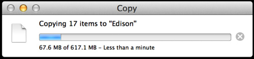
- Wait until the progress bar is complete and a success message is displayed. You have now successfully flashed your board.
Example of the firmware flashing progress:

Example of the success message:

Using the command line with Flash Tool Lite
The Flash Tool Lite provides a command line interface for flashing your board. To use this tool, navigate to the location where you have installed Flash Tool Lite (for example, C:\Program Files (x86)\Intel\Phone Flash Tool Lite) and run the binary file for the command line tool, which is phoneflashtoollitecli.
All command line options are listed in the tool's help message. To view these options, enter the command:
phoneflashtoollitecli --help
Note that the -f option is a mandatory option; this command line tool is designed to flash a single device. Multiple instances of the phoneflashtoollitecli tool can be run simultaneously.
Flashing your firmware manually
Note: Flash Tool Lite is the preferred method of flashing your board firmware. If you run into difficulties, need to revert or have other issues, use this manual process to proceed.
This section contains steps to update (flash) the firmware on your Intel® Edison board using the manual process. The firmware is your board's operating system, and also allows for use of Wi-Fi*, Bluetooth*, analog and digital controls, and other functions. It's important to keep your firmware up-to-date to ensure the best stability and performance for your board.
Flashing the firmware on a system with Windows* (manual process)
Note: The new Flash Tool Lite replaces this method of flashing your firmware. Use this information only if you want to flash your firmware manually, without using Flash Tool Lite.
This guide contains steps to update (flash) the firmware on your Intel® Edison board. The firmware is your board’s operating system, and also allows for use of Wi-Fi*, Bluetooth*, analog and digital controls, and other functions. It’s important to keep your firmware up-to-date to ensure the best stability and performance for your board.
Requirements
- You have assembled your board and connected it to your system. For steps, see the appropriate link below:
- You have installed the appropriate drivers for your system. For steps, see Installing drivers for your Intel® Edison board on a system with Windows*.
- You have set up a serial terminal for your board. For steps, see Setting up a serial terminal on a system with Windows*.
- Once you have connected your board, you should see a drive called Edison show up in Windows Explorer. Remember this drive letter (in this example it is D:) for later use.
Remove old images
- Open a new command window by clicking Start. Type
cmdand press Enter. - Type the Edison drive letter that you noted earlier and press Enter.
- Enter the command:
del *
At the prompt, typeyand press Enter. - All files should now be removed. To confirm, type
dirand press Enter to view files on the drive.
Download the latest image
- Download the latest Yocto* complete image from the main Intel® Edison board downloads page: https://software.intel.com/iot/hardware/edison/downloads.
- Unzip the contents and move these files into the Edison drive. If necessary, overwrite any existing files.


- Verify that your Edison drive contains the new files, as shown below:

Flashing your board
- Open Device Manager by clicking Start and typing
Device Manager.
- Scroll down to Ports (COM & LPT) and take note of the COM number listed under USB Serial Port (COM#). In this example, it is COM7.
- Open the PuTTY.exe application that you previously downloaded, then do the following:
- Under Connection type, select Serial.
- In the Serial line field, enter the COM# for your board, such as COM12.
- In the Speed field, type
115200.

- Click Open.
- A blank screen is displayed. Press Enter two times.

- Type
rootand press Enter. If you already defined a user name and password for your board, enter the appropriate credentials.
-
Enter the command:
reboot ota
Warning: This will erase everything on your board, including configuration settings. - Your board reboots and begins the flashing process with the latest image. When the flashing process is finished, you should see this screen:

Configure your user name and password
Because you have just flashed the image on your board, any previous configuration settings you have configured, such as your user name, password, and Wi-Fi* network options, need to be configured again.
- To assign your board a name, enter the command:
configure_edison --name - Create a login password for your board by entering the command:
configure_edison --password
Flashing the firmware on a system with Mac* OS X* (manual process)
Note: The new Flash Tool Lite replaces this method of flashing your firmware. Use this information only if you want to flash your firmware manually, without using Flash Tool Lite.
This guide contains steps to update (flash) the firmware on your Intel® Edison board. The firmware is your board’s operating system, and also allows for use of Wi-Fi*, Bluetooth*, analog and digital controls, and other functions. It’s important to keep your firmware up-to-date to ensure the best stability and performance for your board.
Requirements
- You have assembled your board and connected it to your system. For steps, see the appropriate link below:
- You have installed the appropriate drivers for your system. For steps, see Installing drivers for your Intel® Edison board on a system with Windows*.
- You have set up a serial terminal for your board. For steps, see Setting up a serial terminal on a system with Windows*.
- Once your board is connected, you should see a drive called Edison show up in Finder.
-

Remove old images
- Open up a new Terminal window.
- Enter the command:
cd /Volumes - To remove all visible files and folders, enter the command:
rm –rf Edison/*
- To remove all hidden files and folders, enter the command:
rm –rf Edison/\.*
Note: If you get a message stating that rm: “.” and “..” may not be removed, this is expected. The “.” and “..” entries are special links to the current directory and parent directory, which may not be removed. - To view files on the mounted Edison drive, enter the command:
ls -lag Edison.
Verify that the files have been removed. - Press Enter. The next line after you press enter should be blank.
Download the latest image
- Right-click the Edison partition and check to see if it is formatted as FAT16.

- If the partition is formatted as FAT16, open Disk Utility and click CD Gadget Media drive. Repartition as an MS-DOS (FAT) partition, as shown in the image below. This changes the partition to FAT32 format.

Note: If you see a Partition failed couldn’t unmount disk message, you left a terminal window open while attempting to partition your Edison drive. Close the terminal before trying to partition the disk.
- Download the latest Yocto* complete image from the main Intel® Edison board downloads page: https://software.intel.com/iot/hardware/edison/downloads.
- Unzip the contents and move these files into the Edison drive.

- Verify that your Edison drive contains the new files, as shown below:
Flashing your board
- Open a new Terminal window.
- Type
screen /dev/cu.usbserial, then press Tab.

- Type
115200 -L.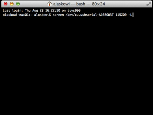
- Press Enter.
- A black screen displays. Press Enter twice.

- Type
rootand press Enter. - If you already defined a user name and password for your board, enter the appropriate credentials.

- Enter the command:
reboot ota
Warning: This will erase everything on your board, including configuration settings. - Your board reboots and begins the flashing process with the latest image. When the flashing process is finished, you should see this screen:

Configure your user name and password
Because you have just flashed the image on your board, any previous configuration settings you have configured, such as your user name, password, and Wi-Fi* network options, need to be configured again.
- Assign your board a name by entering the command:
configure_edison --name - Create a login password for your board by entering the command:
configure_edison --password
Flashing your board (alternate method)
- Install Homebrew by entering the command:
ruby -e "$(curl -fsSL https://raw.githubusercontent.com/Homebrew/install/master/install)" - Install dfu-util, coreutils, and gnu-getopt by entering the command:
Note: Steps 1 and 2 above need to be done only once on a system with Mac OS X.brew install dfu-util coreutils gnu-getopt - Download the latest Yocto* complete image from the main Intel® Edison board downloads page: https://software.intel.com/iot/hardware/edison/downloads.
- Extract the contents of the image file.
- In your terminal, navigate to the directory where you extracted the Linux image. For example:
cd ~/Downloads/edison-image-ww36-14 - Flash your board by entering the command:
The script can take up to 5 minutes to complete the flashing process../flashall.sh - Plug the USB cable in to your board.
Flashing the firmware on a system with Linux* (manual process)
Note: The new Flash Tool Lite replaces this method of flashing your firmware. Use this information only if you want to flash your firmware manually, without using Flash Tool Lite.
This guide contains steps to update (flash) the firmware on your Intel® Edison board. The firmware is your board’s operating system, and also allows for use of Wi-Fi*, Bluetooth*, analog and digital controls, and other functions. It’s important to keep your firmware up-to-date to ensure the best stability and performance for your board.
Requirements
- You have assembled your board and connected it to your system. For steps, see the appropriate link below:
- You have installed the appropriate drivers for your system. For steps, see Installing drivers for your Intel® Edison board on a system with Windows*.
- You have set up a serial terminal for your board. For steps, see Setting up a serial terminal on a system with Windows*.
- Once you have connected your board, you should see a drive called Edison show up in Files. You will want to use /media/username/Edison, not /media/psf/Edison.
Remove old images
- Open up a new Terminal window.
- Enter the command:
cd /media/username - Type
lsand press Enter. Verify that the Edison directory is in the list. - To remove all visible files and folder, enter the command:
rm –rf Edison/*
- To remove all hidden files and folders, enter the command:
rm –rf Edison/\.*
- To view files on the mounted Edison drive, enter the command:
ls -lag Edison.
Verify that the files have been removed.
Download the latest image
- Download the latest Yocto* complete image from the main Intel® Edison board downloads page: https://software.intel.com/iot/hardware/edison/downloads
- Unzip the contents and move these files into your Edison drive.

- Verify that your Edison drive contains the new files, as shown below:

Flashing your board
- Open up a new Terminal window.
- If you do not have screen installed, install it now by opening a new Terminal window and entering the command:
sudo apt-get install screen
You may need to enter your password.
- To connect to your board, enter the command:
sudo screen /dev/ttyUSB0 115200.
You may need to enter your password.
- When you see a blank screen, press Enter twice.

- If you already defined a user name and password for your board, enter the appropriate credentials.
- Enter the command:
reboot ota
Warning: This will erase everything on your board, including configuration settings.
- Your board reboots and begins the flashing process with the latest image. When the flashing process is finished, you should see this screen:

Configure your user name and password
Because you have just flashed the image on your board, any previous configuration settings you have configured, such as your user name, password, and Wi-Fi* network options, need to be configured again.
- Assign your board a name by entering the command:
configure_edison --name - Create a login password for your board by entering the command:
configure_edison --password
Flashing your board (alternate method)
- To install dfu-util, which is an open source program that implements the USB DFU (USB Device Firmware Upgrade) protocol, enter the command:
sudo apt-get install dfu-util - Download the pre-built Yocto image for your board with the most recent available on the main downloads page: https://software.intel.com/iot/hardware/edison/downloads
- Extract the contents of the image file.
- To flash your board and then connect your board to your system using the USB2.0 cable, enter the command:
./flashall.sh
The script can take up to 5 minutes to complete the flashing process.
Setting up a serial terminal
This section provides steps to set up a serial terminal to communicate with your Intel® Edison board. Though serial communication is not strictly required to begin programming on your board, it gives you access to a wide range of functionality useful to any serious developer, such as:
- Connecting your board to a Wi-Fi* network
- Setting a password for your board
- Identifying your board's IP address
- Checking the version of the firmware on your board
- Updating the I/O and sensor libraries on your board to get access to the latest batch of supported sensors
It is therefore strongly recommended that you be able to set up serial communication with your board.
Setting up a serial terminal on a system with Windows*
This section contains steps to set up serial communication with your board.
Requirements
- You have assembled your board and connected it to your system. For steps, see Assembling and connecting your board.
- You have installed the appropriate drivers for Windows. If you have already run the integrated installer for 64-bit Windows*, the installer has already done this for you.
- You have flashed the firmware on your board. For steps, see Flash Tool Lite.
Set up PuTTY
- Download the PuTTY terminal emulator: http://the.earth.li/~sgtatham/putty/latest/x86/putty.exe.
- Double-click the putty.exe file you downloaded to run it.
- Configure the PuTTY menu as follows:
- Under Connection type, select Serial.
- In the Serial line field, enter the COM# for your board, such as COM12.
Note: If you did not note your COM# earlier, navigate to the Device Manager and check for an entry called USB Serial Port (not Intel Edison Virtual Com Port). The COM# is displayed next to the USB Serial Port entry, as highlighted below.
- In the Speed field, type
115200.
- Click Open.
- When you see a blank screen, press the Enter key twice. A login prompt is displayed.

- At the login prompt, type
rootand press Enter. - Press Enter when prompted for a password. You should see a terminal prompt.

You have now established serial communication with your board.
Setting up a serial terminal on a system with Mac* OS X*
This section contains steps to set up serial communication with your board.
Requirements
- You have assembled your board and connected it to your system. For steps, see Assembling and connecting your board.
- You have flashed the firmware on your board. For steps, see Flash Tool Lite.
- Launch Spotlight by pressing Cmd + Space.
- Type
terminal. - Select the Terminal app.
- In the Terminal window, enter the command:
ls /dev/cu.usbserial-*
- In the list of connected devices, look for a device that contains cu.usbserial. In the example above, the device name is /dev/cu.usbserial-A402YSYU.
Note: If your device is not in the list, verify that your board is powered on and connected to your system. For steps, see the appropriate link below: - Connect to the USB serial device using the Terminal screen utility by entering the command:
screen /dev/xx.usbserial-XXXXXXXX 115200 –Lwhere
/dev/xx.usbserial-XXXXXXXXis replaced by your device’s unique name. Using the example above, the command would be:screen -L /dev/cu.usbserial-A402YSYU 115200 –LNote: Adding –L to the command, as shown above, turns on output logging so you can see what the result of your commands are. To end a session in Screen type Ctrl + A and then Ctrl + K to kill the session. You will be prompted to end the session.
- At the blank screen, press Enter twice. A login screen is displayed.
- At the login prompt, type
rootand press Enter. - Press Enter when prompted for a password. The following screen is displayed:
You have now established serial communication with your board.
Setting up a serial terminal on a system with Linux*
This section contains steps to set up serial communication with your board.
Requirements
- You have assembled your board and connected it to your system. For steps, see Assembling and connecting your board.
- You have flashed the firmware on your board. For steps, see Flash Tool Lite.
- If you do not have the screen shell session manager installed, open a new Terminal window. Enter the command:
sudo apt-get install screenIf prompted, enter your password.
- To connect to the board, enter the command (where ttyUSB0 is your connected device):
sudo screen /dev/ttyUSB0 115200If prompted, enter your password to continue.
- Press Enter twice. A login screen is displayed.
- At the login prompt, type
rootand press Enter. - Press Enter when prompted for a password. The following screen is displayed:

You have now established serial communication with your board.
Connecting to a network
This section contains steps to set up network access to your Intel® Edison board and obtain your board's IP address. Connecting your board to a network allows your system to communicate with your board for programming and debugging purposes.
Connecting your Intel Edison board using Wi-Fi*
This guide contains steps to set up Wi-Fi* network access to your Intel® Edison board and obtain an IP address.
Requirements
- You have assembled your board and connected it to your system. For steps, see Assembling and connecting your board.
- If your system has Windows*, you have installed the appropriate drivers for Windows. If you have already run the integrated installer for 64-bit Windows, the installer has already done this for you.
- You are familiar with how to establish serial communication with your board.
- You have flashed your firmware.
Set up Wi-Fi
- Establish a serial communication session with your board.
- To configure your Wi-Fi, enter the command:
configure_edison --wifi
If you get an error saying configure_edison: not found, you need to update your firmware. For steps, see Flashing the firmware with Flash Tool Lite. - When asked if you want to set up Wi-Fi, type
Yand press Enter. - Your board will scan for Wi-Fi networks for 10 seconds. When it is finished, a list of available networks will be displayed. If you don’t see any networks, enter
0to rescan.

- Choose the network you would like to connect to, type the corresponding number from the list, and press Enter. To confirm your entry, type
Yand press Enter. In this example, to connect to the kafka network, enter16.

- If your network requires a password or other information, enter the appropriate network credentials.
- The board will attempt to make a connection to the network. When you see a Done message, your board is connected to a Wi-Fi network.

- Note the IP address, as shown in the image above. This is your board’s IP address. Alternately, enter the command:
ifconfig

Make note of your wlan0 IP address, as shown above. - To verify connectivity, you may want to ping your board from another computer on the same network using the IP address obtained above. Alternately, you can try accessing your board by typing in your IP address into a browser of another computer on the same network.
If you are having problems connecting, try running the following commands in a serial communication session with your board:
ifconfig usb0 down
ifconfig wlan0 down
ifconfig usb0 up
ifconfig wlan0 up
You may also want to try the alternate method to set up Wi-Fi.
Connecting to your Intel® Edison board using Ethernet over USB
When you are in a busy or restricted network environment, you can connect to the Intel® Edison board using a micro-USB cable and a virtual Ethernet connection, known as Ethernet over USB. This document will guide you through connnecting to your Intel® Edison board using Ethernet over USB and obtaining an IP address for the board.
Ethernet over USB allows you to program your board offline using the IDEs included with the Intel® IoT Developer Kit. Using this method will disable your computer's Wi-Fi* connection as long as Ethernet over USB is being used. Ethernet over USB uses the RNDIS protocol.
Ethernet over USB is supported for systems with Windows* or Linux*.
Requirements
- You have assembled your board and connected it to your system. For steps, see Assembling and connecting your board.
- If your system has Windows, you have installed the appropriate drivers for Windows. If you have already run the integrated installer for 64-bit Windows, the installer has already done this for you.
- Your Intel® Edison board must have the microswitch toggled down towards the micro-USB ports.
Choose your operating system
Instructions for Windows*
This section contains steps to update your system's network adapter configuration with a static IP address to use Ethernet over USB.
- View your Network Connections, as follows:
- In Windows 7 and below, go to the Control Panel. Under Network and Internet, click View network status and tasks. Click Change Adapter Settings in the sidebar.
- In Windows 8, right-click the Windows Start menu button and select Network Connections.
- Plug the micro-USB cable into the micro-USB port closest to the middle of the board. Plug the other end of the cable in to your computer.
- Look for a network adapter with the label RNDIS. Right-click the network adapter, then select Properties to configure its IP address.
- From the list, select IPV4.
- Change the IP information as follows:
- IP:
192.168.2.2
If you get a system notification that 192.168.2.2 is taken, try any IP address from 192.168.2.1 to 192.168.2.14. Do not use 192.168.2.15. - Mask:
255.255.255.0
- IP:
You can now ping your Intel® Edison board on address 192.168.2.15 from your computer's command line. You can now also use PuTTY to SSH into the board at the same IP address.
If you are using the Intel® XDK IoT Edition, the IDE should automatically detect your board. Connect to your board using the IP address 192.168.2.15 to upload your programs.
Instructions for Linux*
This section contains steps to set up Ethernet over USB by forwarding connections to the IP address 192.168.2.2 through the USB cable.
- Open a new Terminal window.
- Plug the micro-USB cable into the micro-USB port closest to the middle of the board. Plug the other end of the cable in to your computer.
- Use the ifconfig command to forward connections to the IP address 192.168.2.2 through the USB cable. Enter the command:
sudo ifconfig usb0 192.168.2.2
You may be prompted for your user password.
You can now ping your board on address 192.168.2.15 from a Terminal. You can now also use Terminal to SSH into the board at the same IP address.
If you are using the Intel XDK IoT Edition, the IDE should automatically detect your board. Connect to your board using the IP address 192.168.2.15 to upload your programs.
Getting started with Access Point (AP) Mode for the Intel® Edison board
Access Point (AP) Mode is a new feature available on firmware releases as of January 2015. The initial release provides the means to perform the initial setup of your board, as well as upgrade firmware as it becomes available.
Notes:
- Running a VPN can interfere with connecting to your board via hostname.
- It may be necessary to shut off a local machine firewall when connecting to your board via hostname.
Requirements
- You have assembled your board and connected it to your system. For steps, see Assembling and connecting your board.
- If your system has WIndows*, you have installed the appropriate drivers for Windows. If you have already run the integrated installer for 64-bit Windows, the installer has already done this for you.
- You have flashed your firmware.
- A laptop/desktop with Wi-Fi* capabilities
- An available Wi-Fi network, with network name, encryption type, and passcode
- Bonjour* Print Services, for systems with Windows. This is required for Windows users to enable mDNS capabilities. To download the Bonjour installer, go to the Bonjour Print Services for Windows page at http://support.apple.com/kb/DL999 and run the installer as an administrator.
The following instructions work best on an Intel® Edison board assembled with the Arduino expansion board. To enter AP Mode with the Intel® Edison mini breakout board, you must establish a serial communication session with your board and use the command line: configure_edison --enableOneTimeSetup.
Entering AP mode and connecting to a Wi-Fi network
- Hold down the button labeled PWR for more than 2 seconds but no longer than 7 seconds. Around 4 seconds is sufficient.
The LED at JS2 near the center of the board should now be blinking. It will remain blinking as long as your board is in AP mode. - In a few moments, a Wi-Fi network hotspot appears. Typically, its name is in the form of: Edison-xx-xx, where xx-xx is the last two places of your board's Wi-Fi mac address. This mac address is on a label within the plastic chip holder that contained the Intel® Edison chipset within the packaging. However, if you have given your board a name, the Wi-Fi hotspot has the same name.
- When you find your board's Wi-Fi hotspot, attempt to connect. The passcode necessary to connect is the chipset serial number, which is also on the label in the plastic chip holder beneath the mac address. Additionally, a small white label on the Intel® Edison chipset itself also states the serial number. The passcode is case-sensitive.
- Once you have connected to the hotspot, open a browser (preferably Firefox or Chrome) and enter
Edison.localin the URL bar. The following screen displays:
Note: If you cannot access Edison.local in your browser, type your board’s IP address directly into the URL bar. To find your board’s IP address, establish a serial communication session with your board and enter the command:
ifconfig - In the New Device Name field, type a host/device name that is unique to your board. To connect to your board in the future, enter
devicename.localin your browser’s URL bar, wheredevicenameis the name of your device. - If required, provide a password. This password replaces the current Wi-Fi password for AP Mode.
- From the Network Name drop-down list, select the Wi-Fi network to connect your board to.
- Select your network protocol and provide any required credentials, such as your user name and password.
- Click Submit to apply your changes and exit AP Mode. You can re-enter AP Mode by holding the PWR button down for about 4 seconds. This allows access to the update link.

Flashing your board
This section contains steps to flash (update) the Yocto* image on your Intel® Edison board using AP Mode.
- Download the image to update your board with, or supply your own image in the form of a .zip file. You can download the latest image for the Intel® Edison board from the following location: https://software.intel.com/iot/hardware/edison/downloads.
- On the board, hold the PWR button down for about 4 seconds. The LED at JS2 near the center of the board blinks to signal that your board is in AP Mode.
- Connect your system to your board's Wi-Fi network.
- Enter
devicename.localin your browser’s URL bar, wheredevicenameis the name of your device. - Click the Upgrade link beneath the Intel logo.

- Click Choose File, navigate to the .zip file location, and then click OK.
- Click Upgrade. Your .zip file is uploaded and the board is updated locally. Follow the on-screen instructions to reconnect to your board’s network when required.
- If prompted, re-enter any required configuration settings, such as a password for your board.
- Click Submit to apply your changes.
Connecting outside of AP Mode
Once AP Mode setup has been completed, you can connect to the board by entering devicename.local in your browser’s URL bar, where devicename is the name you gave your board during setup. Your board turns this into the hostname for the board and web purposes.
If you are having difficulties connecting using a system with Windows, you may not have Bonjour Print Services set up. Download Bonjour as described in the Requirements section and reboot your system. Once complete, you should be able to connect.
- On the board, hold the PWR button down for about 4 seconds. The LED at JS2 near the center of the board blinks to signal that your board is in AP Mode.
- Connect your system to your board's Wi-Fi network.
- Enter
devicename.localin your browser’s URL bar, wheredevicenameis the name of your device.
Resources
Start inventing today with the Intel® IoT Developer Program which offers knowledge, tools, kits and a community of experts to quickly and easily turn your innovative ideas into IoT Solutions.
Dream it, Build it with the Intel® IoT Developer Kit for Intel® Edison and Intel® Galileo platforms. These kits are versatile, performance-optimized and fully integrated end-to-end IoT solutions supporting a variety of programming environments, tools, security, cloud connectivity and hardware.
For more resources and to learn how the new Intel® IoT Developer Kit v1.0 can help streamline your IoT projects:
- Download the Intel® IoT Developer Kit
- Visit the Intel® Developer Zone for IoT
- Attend one of our Roadshows for hands-on training in creating your own IoT projects