
A First Impression of a clockwork using Simple Gears
We wanted a first impression of a clockwork using simple gear for visual evaluation. A provisory prototype is made.
Introduction
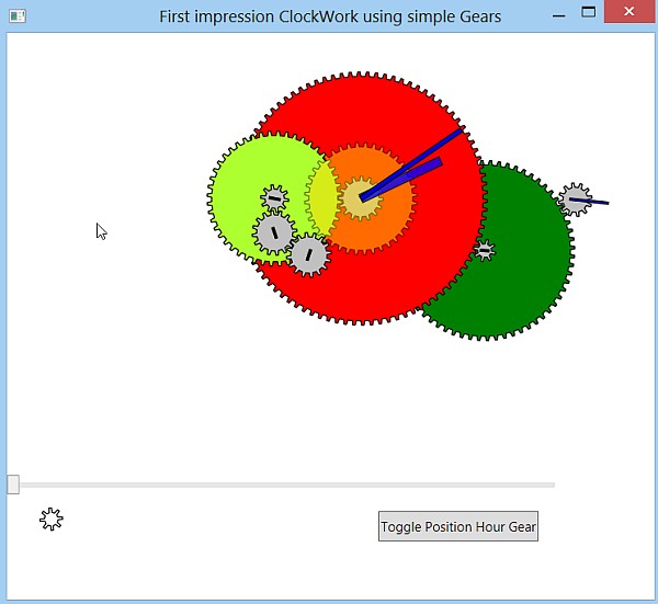
I wanted a first impression of how a clock made with gears would look. After adding a few gears, it was obvious that the rotation speed of most gears is too slow to make a cool impression. Anyhow, I provisory finished the first trial and wrote this tip/trick about it. If you want to see it running, download the .exe. Note that the code is a first (and only) trial iteration for a first visual impression, don't expect a top visual design or exemplary correct or generalized code.
Background
Nowadays a lot of JavaScript frameworks/libraries are being developed. jQuery is a well known sample (Tip: We even have now XamlQuery for WPF!). D3 is a less known JavaScript library for visualization. It contains visualization components, models data and couples data to DOM manipulation. I was impressed by the d3 wiki Gallery with many samples, like Bubble Chart, Collision Detection, Epicyclic Gearing (allow JavaScript in all samples). The epicyclic gearing was cool and I wondered how a clock would look. Since my skills in D3.js are non existent, I decided to make a prototype in WPF.
There are already many articles in WPF over clocks, I used the example of Analog Clock in WPF for setting the angles of the Gears. For the first impression, I decided to use gears with a simple tooth profile, see Draw gears in C#. The gear ratios used for the clock were taken from Gary's clocks. Note that building a clockwork is a strange hobby, but some people build even a planetarium in their own home, see the current state of this planetarium here.
Simple Gears
After first trial and error in the Main Window, a UserControl is used, see the Gear.xaml code below. The GearPath.Data will be overwritten in code behind by a gear shape. In the code behind WPF dependency properties NrTeethProperty, RotationAngleProperty, ShiftAngleProperty and FillProperty are defined. These properties can be set in MainWindow.xaml where Gear User Controls are used. RotationAngle (will later be set by a timer for live rotation) and Fill are used for binding in Gear.xaml.
<UserControl x:Class="ClockGear.Gear"
             x:Name="thisGearName"
             ....>
    <Grid>
        <Path x:Name="GearPath"
            Stroke="Black" StrokeThickness="1" Fill="{Binding ElementName=thisGearName, Path=Fill}"
            Data="M 0,0 L 0,20 M 0,0 L 0,-20 M 0,0 L 20,0 M 0,0 L -20,0">
            <Path.RenderTransform>
                <TransformGroup>
                    <RotateTransform Angle="{Binding ElementName=thisGearName, Path=RotationAngle}" />
                </TransformGroup>
            </Path.RenderTransform>
        </Path>
    </Grid>
</UserControl>
The dependency properties NrTeeth and ShiftAngle (Initial shift of the Gear angle, 0..100 = one toothwitdh) specify the Gear. Their PropertyChangedCallback function calls DrawGear. See some code snippets of Gear.cs below.
For the first impression, we used a very simple tooth profile, this could be refined in a next iteration. We copied the Gear from Draw gears in C#, see the figure on that page for the definition of the angles used. Radians are used instead of degrees and in DrawGear linear lines are used to connect all points as a first approximation. See some code snippets of Gear.cs below.
//Codesnippets from Gear.xaml.cs

public partial class Gear : UserControl
{
    // Fixed for all gears. radius computed from nrTooth, profile radius-toothdepth .. radius
    public const float toothWidth = 8;
    public const float toothDepth = 6;
    public const float chamfer = 1;
    ....
    // Define dep. properties NrTheeth, RotationAngle, ShiftAngle, Fill

    public static readonly DependencyProperty NrTeethProperty =
        DependencyProperty.Register("NrTeeth", typeof(int), typeof(Gear),
        new PropertyMetadata(new PropertyChangedCallback(OnGearChanged)));

    public int NrTeeth
    {
        get { return (int)this.GetValue(NrTeethProperty); }
        set { this.SetValue(NrTeethProperty, value); }
    }

    public static void OnGearChanged(object sender, DependencyPropertyChangedEventArgs args)
    {   ...
        thisOne.GearPath.Data = DrawGear(nt, ia);
    }

    private static Point PointFromCircle(double radius, double angle)
    .....

    public static PathGeometry DrawGear(int nTeeth = 90, float initAngle = 0)
    {
        float pi = (float)Math.PI;
        float radius = (toothWidth * nTeeth) / (2 * pi);

        // dtheta angle single tooth;  nTeeth*2*dtheta full circle
        float dtheta = (float)(Math.PI / nTeeth);
        float phi = dtheta * (chamfer) / (toothWidth);
        float alpha = dtheta * (toothWidth - 2.0F * chamfer) / (toothWidth);

        PathGeometry Result = new PathGeometry();
        PathFigure figure = new PathFigure();
        figure.IsClosed = true;

        // Set startAngle for the beginning of the first tooth.
        float startAngle = -dtheta / 2 + initAngle;
        float degrees = (float)(startAngle - phi);

        // Make a path representing the gear.
        for (int i = 0; i < nTeeth; i++)
        {
            // make 4 line segments

            // 1) line form smaller radius to larger radius
            LineSegment segment1 = new LineSegment();
            segment1.Point = PointFromCircle(radius, degrees + phi);
            figure.Segments.Add(segment1);

            // set startpoint as first Point so it is skipped.(Figure.IsClosed).
            if (i == 0) figure.StartPoint = segment1.Point;

            ....
            segment2.Point = PointFromCircle(radius, degrees + phi + alpha);
            ....
            segment3.Point = PointFromCircle(radius - toothDepth, degrees + dtheta);
                ....
            segment4.Point = PointFromCircle(radius - toothDepth, degrees + 2 * dtheta);
            ....

            degrees += 2 * dtheta;
        }
        Result.Figures.Add(figure);
        return Result;
    }
}
Hands
A similar approach is followed for the Hand UserControl. It has a Dependency Property called RectangleProperty, which is used to set the Path.
ClockWork
Now we will compose a clockwork using Gear and Hands. The first question is what Gears we should use? The second hand should rotate once every 60 seconds, the minute hand should rotate once every 60*60 seconds. So there is a 1:60 ratio between the minute and second hand. If we take a 8 tooth second gear, we need a 8*60=480 tooth minute gear. This is a very large gear, it is better to obtain the ratio transmission in a few smaller steps. We took the gear ratio's form Gary's clocks, see the next image using non overlapping gears (in the program, press the button)
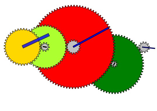
We see the following transmission ratio: (Gray most left second gear)*(Dark Green and little Gray gear)*(Dark Red Minute Gear)= (1/12)*(64/8)*(90/1) = 60. For the hour hand and the minute hand, we need a ratio of 12: (Gray Minute gear)*(MintGrean Gear)*(Gold Hour Gear) = (1/16)*(48/10)*(40).
In the default display of the program, the hour gears and minute gears have the same center and two extra transfer gears are used, that have no influence on the gear ratios. Note that in a 2D setting, it is difficult to present the overlapping minute and hour gears in a clear way. This is only possible in a 3D setting, with hollow shafts, etc. Note also that all the gears can be placed freely in a sequential way, but the transfer gears have also a fixed end position. I hacked a little by hand but I assume an analytic solution can be found.
The next step is to implement the clockwork using the gears and hands. It is possible to model composed units with [optional] Gears and Hands with the same rotational speed, but I choose to start with the basic Gears and Hands. The RotationAngle of the named Gears and Hands is set directly in code behind, see code snippet. A next iteration would be to introduce a ViewModel with common ShaftAngles and bind these to the RotationAngle of the Gears and Hands.
private void Timer_Tick(object sender, EventArgs e)
{
    var DateTime = System.DateTime.Now;

    float hour = DateTime.Hour;
    float minute = DateTime.Minute;
    float second = DateTime.Second;

    float hourAngle = 30.0F * hour + minute / 2.0F + second / 120.0F;
    float minuteAngle = 6.0F * minute + second / 10.0F;
    float secondAngle = 6.0F * second;

    G1.RotationAngle = (float)secondAngle;
    H1.RotationAngle = (float)secondAngle;

    float x1 = -(second +minute*60 + hour*60*60) *6.0F * 12.0F / 64.0F;
    G2.RotationAngle = x1;
    G3.RotationAngle = x1;
    H2.RotationAngle = x1;
    ......
}
To construct the clockwork, we have a festival of named hands, gears and manual fine-tuning (=hacking), see a snippet of the MainWindow. We use a Canvas and we place the common hand and gears in common Grids, so they are displayed at the same position at the top of each other. We manually set the Canvas.Left and Top position of the grid and use ShiftAngle if needed. Finally the ZIndex is set for the correct visibility of the Gears and Hands. It may be possible to model and set the "Layer/Depth" of an element.
// A snippet from MainWindow.xaml

<Canvas>

   <Grid x:Name="Seconds" Canvas.Left="530" Canvas.Top="150" Panel.ZIndex="10" ToolTip="12 - Seconds"  >
      <vw:Gear  x:Name="G1" NrTeeth="12" Fill="Silver" />
      <vw:Hand x:Name="H1" Rectangle="-1,-30,2,35" Fill="Blue" />
   </Grid>

   <Grid Canvas.Left="452" Canvas.Top="197" ToolTip="8*64" >
       <vw:Gear  x:Name="G2" NrTeeth="64"  Fill="Green" />
       <vw:Gear  x:Name="G3" NrTeeth="8" ShiftAngle="20" Fill="Silver"/>
       <vw:Hand  x:Name="H2" Rectangle="-1,-4,2,8" Fill="Black" />
   </Grid>
Points of Interest
- The rotation speed of most gears is to slow for a really cool effect.
- The overlapping minute and hour gears cannot be presented in a clear way in a 2D setting.
- Some planned refinements are given this first impression useless: a more advanced tooth profile (note that given one turning direction, we have a lot of freedom at the "backside" of the tooth), more realistic looking fill of the gears, sounds tick-tack and a hourly boink, display in a W8.1 Modern StartMenu tile.
- On close examination, we see some overlapping tooth. When two large gears interact, no problems arise. We should examine the theory of gears more closely (Tooth width, chamfer and Depth) or examine the code (for example, take into account the
StrokeThicknessof the border). - For a stopwatch or timer, we could use faster turning gears, a storyboard may be more efficient.