
Retro Game Cartography
5.00/5 (11 votes)
An algorithm for reconstructing game world map from captured game play

Introduction
The algorithm recreates a game world from video capture of gameplay, so it is universal as it does not depend on game's internal representation of its world. To achieve this, we scan each frame of gameplay and extract features that we are using to find our position in the world. We keep database of identified features, called sketch, which we update with each new frame we process. Once the frame's location is determined and sketch is updated, we store frame's image data combined with motion information. We use motion information to remove moving objects from the final map.
Since it operates on video output, certain restrictions apply to gameplays that can be supported:
- Video has limited number of colors (up to 16)
- Gameplay have to continuously scroll over the game's world
- Example of supported gameplay: CJ's Elephant Antics
- Example of gameplay that is not supported: Cybernoid
- Each part of the world needs to have enough distinguishable features and their layout has to be unique
We can see some example of generated maps:
Before we start, please note that the algorithm and its implementation is not optimized enough to support real-time mapping, as it needs more time to process gameplay video than to record it.
Since this is only a demonstration of the algorithm, not fully fledged "product", user-friendliness of the final application was not considered. Application operates on ZIP files that are storing individual frames as separate files. Frames stored in archived files has no specific format, they are just raw captures of pixels from the video output of predefined size. Pixels stored in fame file are not in RGB format, but platform specific color values.
In this implementation, everything (size screen, color palette, etc.) is fixed to support Commodore 64 video output. All gameplay files provided are grabbed playing games on C++ port of this emulator.
Since we got these technicalities out of our way, we can proceed with the description of the algorithm.
Determining Active Window
The first thing we need to figure out is the active area of the screen which displays part of game world. We operate under the assumption that there is a single such area and that it is the largest one on the screen. The rest of the screen we ignore as it, most probably, displays HUD.
To determine active window, we scan changes between frames and keep a matrix that stores detected changes for each pixel on screen. Each time we detect change of a pixel color between frames, we mark them in this matrix. After each update, we are extracting islands (contours) of changed pixels, searching the largest one. Contour extraction is explained in this section.
We are looking for a contour that covers at least a third of total screen pixels, but we will keep scanning frames as long as this area keeps increasing. We stop scanning only after we have not detected size increase of the largest contour for 100 consecutive frames. When that happens, bounding rectangle of the contour is declared as active window.
Window module implements logic for determining active window. The module defines the following entities:
Pendingrecord – that keeps the state of the window scanning process: change-of-pixels matrix, size of the largest contour and its bounding rectangle...Windowrecord – represents finalized active window: bounding rectangle with the list of frames that had been scanned.WindowStatediscriminated union – result ofupdatefunction.updatefunction – that processes current frame and updates the state of windows scanning process. If the criteria for declaring active window has been reached, function will returnComplete Window, otherwise the result will beIncomplete Pendingto indicate failure.
Creating Map
Once the window into our game world has be determined, the map stitching can begin.
The basic idea is to identify features in the current frame and match them against the database of already identified features, called sketch, to determine the location of the current frame in the game world. We deal with two kinds of features: corners and contours.
Extracting Features
Original images are not suitable for feature extraction as they contain too many information. Game worlds are made to be pretty and colorful, but that unfortunately introduces a lot of "noise" for our needs. So in order to reduce amount of information we are dealing with and number of extracted features, we apply median filter to source image. We use 5x5px window to do the filtering:
 | > |  |
| Original image
| Filtered image
|
Filter module contains median function that implements median filter.
Feature module defines few data types that are used for representation of features for different purposes:
Featurerecord - stores feature's position and areaFidalias - description of the feature (e.g., for corners, it represents color of all surrounding pixels)Handlealias - unique definition of the feature: its description, position and area
Corners
In computer vision, corners are usually the most interesting parts of the image. We are going to use them as landmarks on our maps to identify position of a frame.
For extraction of corners, we are not going to use any of the fancy algorithms, but a simple implementation that only inspects neighboring pixels. For each pixel in the frame, we take 3x3px window and inspect pixels in it. Only following patterns are recognized as corners:

Please note that corner identification operates on frames that have been processed by median filter.

Once a corner has been identified, we are switching to non-filtered image and take 5x5pixels window at corner's position to create its description. We are converting color values in this window to array of bytes and from there to an integer number. That number will be feature description. We combine the description with corner's position to uniquely identify a corner. Area is added to the mix to satisfy Feature contract, but that information is not that useful to us, because all corners will have the same area that corresponds to window size.
Corner module defines extract function that will extract corners from the image and return them as list of features.
Contours
Contours represents connected pixels of the uniform color. In our algorithm, we are using them for identifying moving parts of the frame, its application is described here. Another application is identifying active window, except we are not processing real frames, but 1-bit pixels that identify whether pixels of the original image had any changes in color during scanning period. That application is described in this section.
Simple 4-way flood fill algorithm with queue is used to identify contours.

Contour module defines functions and data types that are dealing with contours:
Contourrecord - stores information about contour: position, area, bounding rectangle, color, ID (contour number in the image) and list of the edge pixels.Buffersrecord - represents buffers used by contour detection algorithm. It also provides some useful information such as map of edge pixels and map of contour IDs.bufferfunction - createsBuffersinstance for that can handle specified image.singlefunction - taking coordinate within image to extract single contour from the image to which specified pixel belongs.extractfunction - extract all contours in the image. It returns all extracted contours as list ofContour.recoverfunction - recreates image from supplied list of contours.encodefunction - createsFeatureobject fromContourinstance.
Building Feature Map
We are keeping all discovered features in a database called sketch. The database has two main parts: pending features and confirmed features. Only confirmed features are used for locating frames. When the feature is first discovered and added to the database, it goes to the pending list. Only after it is determined that the same feature exists at the same location for certain number of successive frames (25), it goes into confirmed list. This is done in an effort to remove features belonging to moving objects.
These two parts are represented by:
- map of all detected features, which maps unique feature to its confirmation state
- multi-map of confirmed features, which maps feature descriptions to list of confirmed locations
The database has two operations:
- find operation that takes a list of features as input and returns the list of matches.
- update operation that updates database with the list of features. All features go through a confirmation process.
List of matches contains feature descriptions found in the confirmed list of the database and their known global locations. If some feature description from the input list is not found, it will not be present in the result set.
As feature extraction process returns feature locations that are local to the processed frame, we need to provide adjustment to sketch update operation. Adjustment is actual global location of the frame to which new features belong. Determining frame location is described in the next section.
The update loop looks like this:
- Extract features from a frame
- Match extracted features against current sketch
- Use matches to determine global location of the frame
- Update sketch with frame features adjusted to actual frame position: we add new features to pending list and move features with enough confirmations to confirmed list

Sketch module defines sketch structure and two of the mentioned operations:
Sketchrecord - represents sketch (feature database)Matchesrecord - feature description matchesfindfunction - find operationupdaterecord - update operation
Determining Location
To determine position of the frame, we use matches that find operation of feature databases has returned. As it was noted, match contains feature description and list of known positions. For each matched feature, we take all known positions and do the adjustment so we get position of top-left corner of the frame. We declare all these positions as candidates for possible position of the frame.
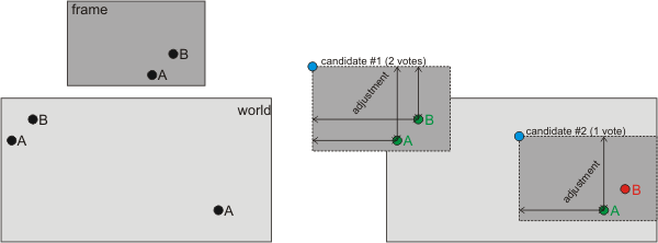
We count number of times each position appears among the candidates and use this count as an input to the formula that scores viability of position. The second parameter in this formula is position's distance from the previous frame's position. We select position with the largest value. The formula we use to calculate position's score looks like this:
After we select a position the best score, we need to verify whether it is acceptable. In order for position to be verified, at least 50% of confirmed features in frame's region must be among the matches. If we get fewer matches in the region, we inform the caller that we failed to determine the frame's position.

Locate module has byFeatureCount function that is responsible for determining position of the frame based on the feature matches.
Detecting Moving Objects
Moving object are making all kind of artifacts on our map, so we need to filter them as much as possible. To do so, we need to detect movement between two consecutive frames. Since two frames can have different global positions, we need to adjust positions and find overlapping area and then do movement detection only in that region.
Once we have made the adjustments, we have two more steps to do. In the first step, we find all contours whose pixels had any changes since the previous frame. In the second step, we create matrix which marks all pixels within bounding rectangles of such contours.
| Frame #1
| Frame #2
|
 |  |
 | |
| Detected motion
| |
Example of motion detection
Motion module defines mark function that takes two consecutive frames and returns matrix that has the regions with detected movement marked.
Plotting Map
So far, we have dealt with stuff needed by algorithm to make sense of the game's world and not it's actual visual representation. This is the final step in our effort to create unified view of the game's world. To do so, we keep a single buffer which stores content of each frame for which we determined location.
Size of the buffer occasionally needs to extended, we do it in increments of active window's height/weight - depending on which dimension needs to be extended. As our first frame has position (0, 0), we also keep coordinates of the real top-left corner of the map. Each time we extend map to the left at the top, we need to update these coordinates.
Content of the current frame cannot just be pasted at determined location as moving objects would leave artifacts all over the map. So instead of keeping just the latest pixel value in map print, we keep history of all possible colors for each pixel. As we operate with the limited number of colors, we keep these values in a simple array. The idea is that each element of the array keeps the weight of a color. Weight is calculated based on the number of times certain color appeared on that location. Each time color is observer, its weight is increased, but only if no movement was detected in the region to which the pixel belongs. If movement was detected, weight of that color will reset.
Two options to generate actual pixel values are available: fast and smoothed. Fast just select color with highest weight, while smoothed option uses values in neighboring cells to perform blur-like operation.
Print module has update function that updates map print with current frame and plot and quickPlot that converts actual map print to an image.
Stitching It All Together
Our last effort is to combine all the stuff discussed previously. The implementation is two modules:
Worldmodule - definesWorldrecord which holds world's sketch (feature database) and map print. It also tracks position of the last located frame.updatefunction is responsible for updating world with each new frame: it locates frame, updates sketch and map print.Stitchermodule - definesloopfunction. It takes sequence of frames and runs algorithm's main loop, creating world representation. It has three steps:- Identifying active window
- Creating representation of game world
- Plotting map print to actual image
Auxiliary Stuff
The following modules define auxiliary data types and functions:
Primitivemodule - definesPointandRectrecords that are used for representing positions and regions in the worldPalettemodule - defines set of functions for converting pixel colors from different pallets and formatsMatrixmodule - definesMatrixclass, that represents matrix used for representing image data and offers basic operation like initialization, resizing…Imagemodule - defines set of functions for converting image data (stored as matrix) to different pallets and formatsFiltermodule - provides implementation of median and blur filtersStitchermodule - hasIStitchingObserverthat can be used to notify external code about progress of the algorithm
Future Work and Improvements
As it was said at the beginning of the article, this is just a proof of concept, it needs more work to be practical and usable for real-time mapping while the game is being played. This is a short list of required improvements:
- Code optimization - as it is obvious, we cannot process world mapping in real-time
- Handling non-overlapping segments - the current implementation cannot handle different segments of the map that are not overlapping. If we are suddenly "teleported" to a different part of the world that has not been mapped yet, we would be "lost". We would not be able to patch our map with that part of the world.
- Inclusion of moving object - finding approach to track moving object and include them into final map print
- Improved filtering of artifacts - as the results show, we are not able to filter all the traces moving objects leave on our maps
Hopefully, some of these points will be addressed in future articles.
History
- 29th July, 2020: Initial version