This project is about controlling a stepper motor and seven segment display via the parallel port. I am going to explain how to control a stepper motor and seven segment display. Here also you can find some more information about the parallel port configuration and such. Also I will describe the seven segment display.
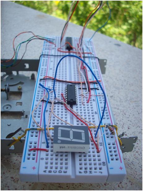
Figure 1 – Circuit
1. What is a Stepper Motor?
A stepper motor is an electromechanical device which converts electrical pulses into discrete mechanical movements. The shaft or spindle of a stepper motor rotates in discrete step increments when electrical command pulses are applied to it in the proper sequence. The motor's rotation has several direct relationships to these applied input pulses. The sequence of the applied pulses is directly related to the direction of motor shaft's rotation. The speed of the motor shaft's rotation is directly related to the frequency of the input pulses, and the length of rotation is directly related to the number of input pulses applied.
1.1 Stepper Motor Advantages & Disadvantages
Of course stepper motor systems are have some advantages & disadvantages. Here you can realize that it comes with so few disadvantages.
Advantages
- The rotation angle of the motor is proportional to the input pulse.
- The motor has full torque at standstill (if the windings are energized)
- Precise positioning and repeatability of movement since good stepper motors have an accuracy of 3% to 5% of a step, and this error is non-cumulative from one step to the next
- Excellent response to starting/stopping/reversing
- Very reliable since there are no contact brushes in the motor. Therefore the life of the motor is simply dependent on the life of the bearing
- The motor's response to digital input pulses provides open-loop control, making the motor simpler and less costly to control
- It is possible to achieve very low speed synchronous rotation with a load that is directly coupled to the shaft
- A wide range of rotational speeds can be realized as the speed is proportional to the frequency of the input pulses.
Disadvantages
- Resonances can occur if not properly controlled
- Not easy to operate at extremely high speeds. For this process you need to use DC motors.
1.2 Stepper motor characteristics
Stepper motors are constant-power devices (power = angular velocity x torque). As motor speed increases, torque decreases. The torque curve may be extended by using current limiting drivers and increasing the driving voltage. Steppers exhibit more vibration than other motor types, as the discrete step tends to snap the rotor from one position to another. This vibration can become very bad at some speeds and can cause the motor to lose torque. The effect can be mitigated by accelerating quickly through the problem speed range, physically damping the system, or using a micro-stepping driver. Motors with greater number of phases also exhibit smoother operation than those with fewer phases. Stepping motors are suitable for translating digital inputs into mechanical motion. In general, there are three types of stepping motor:
- VR (Variable Reluctance) stepping motors
- Hybrid Stepping motors
- PM (Permanent Magnet) Stepping motors

Table 1. Stepping Motor Characteristics Comparison
Figure 2 and 3 are used to explain the operation of a simplified stepping motor (90°/step). Here the A coil and B coil are perpendicular to each other. If either A or B coil is excited (a condition which is known as single-phase excitation), the rotor can be moved to 0°, 90°, 180°, 270° degree position depending on the current’s ON/OFF conditions in the coils.
Figure 2 - Single-phase excitation
Figure 3 - Single-phase coil schematic
1.3 Two-phase stepper motors
There are two basic winding arrangements for the electromagnetic coils in a two phase stepper motor: bipolar and unipolar.
Unipolar Motors
A unipolar stepper motor has logically two windings per phase, one for each direction of current. Since in this arrangement a magnetic pole can be reversed without switching the direction of current, the commutation circuit can be made very simple (e.g. a single transistor) for each winding. Typically, given a phase, one end of each winding is made common: giving three leads per phase and six leads for a typical two phase motor. Often, these two phase commons are internally joined, so the motor has only five leads.
Figure 4 – It is possible to take a stepper motor from an old floppy drive
A microcontroller or stepper motor controller can be used to activate the drive transistors in the right order, and this ease of operation makes unipolar motors popular with hobbyists; they are probably the cheapest way to get precise angular movements. (For the experimenter, one way to distinguish common wire from a coil-end wire is by measuring the resistance. Resistance between common wire and coil-end wire is always half of what it is between coil-end and coil-end wires. This is due to the fact that there is actually twice the length of coil between the ends and only half from center - the common wire - to the end.)
Unipolar stepper motors with six or eight wires may be driven using bipolar drivers by leaving the phase commons disconnected, and driving the two windings of each phase together. It is also possible to use a bipolar driver to drive only one winding of each phase, leaving half of the windings unused.
Bipolar motor
Bipolar motors have logically a single winding per phase. The current in a winding needs to be reversed in order to reverse a magnetic pole, so the driving circuit must be more complicated, typically with an H-bridge arrangement. There are two leads per phase, none are common.
Static stictional effects using an H-bridge have been observed with certain drive topologies. See DuBord phenomenon. Because windings are better utilised, they are more powerful than a unipolar motor of the same weight.
8-lead stepper
An 8 lead stepper is wound like a unipolar stepper, but the leads are not joined to common internally to the motor. This kind of motor can be wired in several configurations:
- Unipolar.
- Bipolar with series windings. This gives higher inductance but lower current per winding.
- Bipolar with parallel windings. This requires higher current but can perform better as the winding inductance is reduced.
- Bipolar with a single winding per phase. This method will run the motor on only half the available windings, which will reduce the available low speed torque but require less current.
The coil schematic of a bipolar stepper motor is shown below:
Figure 5 - Bipolar Stepper motor Coil schematic
Sending 1011 to the AABB pins will rotate the motor to a particular location, by energizing Coil A in a particular direction. Then rotating this sequence to 0111, will energize Coil B in the same direction. Motor will turn by another step. Then, another rotated sequence of 1110 will energize the Coil A with a reversed direction as compared to the previous one, so the motor will continue with another step in the same direction. Then 1101 will energize the Coil B in the reverse direction, and one full rotation will be completed, if the rotor has only two teeth. However, commercial motors have more than two teeth, and they turn by steps of typically 1.8° instead of 90°.
2. What is SN74LS47?
The SN74LS47 are Low Power Schottky BCD to Seven-Segment Decoder /Drivers consisting of NAND gates, input buffers and seven AND-OR-INVERT gates. They offer active LOW, high sink current outputs for driving indicators directly. Seven NAND gates and one driver are connected in pairs to make BCD data and its complement available to the seven decoding AND-OR-INVERT gates. The remaining NAND gate and three input buffers provide lamp test, blanking input / ripple-blanking output and ripple-blanking input. The circuits accept 4-bit binary-coded-decimal (BCD) and, depending on the state of the auxiliary inputs, decodes this data to drive a seven-segment display indicator. The relative positive-logic output levels, as well as conditions required at the auxiliary inputs, are shown in the truth tables. Output configurations of the SN74LS47 are designed to withstand the relatively high voltages required for seven-segment indicators.
Here in Figure 6 you can see connection diagram of SN74LS47 and pin information. You will find the circuit diagram later on the document. With truth table (Figure 7) you can find out what values are for which letter. Since the SN74LS47 is a BCD converter the table is going to be needed to make work easier.
Figure 6 – SN74LS47 Connection Diagram
Figure 7 – Truth Table for BCD Conversion
2.1 The BCD Number System
You should now be familiar with the Binary, Decimal and Hexadecimal Number System. If we view single digit values for hex, the numbers 0 - F, they represent the values 0 - 15 in decimal, and occupy a nibble. Often, we wish to use a binary equivalent of the decimal system. This system is called Binary Coded Decimal or BCD which also occupies a nibble. In BCD, the binary patterns 1010 through 1111 do not represent valid BCD numbers, and cannot be used.
Conversion from Decimal to BCD is straightforward. You merely assign each digit of the decimal number to a byte and convert 0 through 9 to 0000 0000 through 0000 1001, but you cannot perform the repeated division by 2 as you did to convert decimal to binary. Let us see how this works. Determine the BCD value for the decimal number 5,319. Since there are four digits in our decimal number, there are four bytes in our BCD number. Since computer storage requires the minimum of 1 byte, you can see that the upper nibble of each BCD number is wasted storage. BCD is still a weighted position number system so you may perform mathematics, but we must use special techniques in order to obtain a correct answer.
3. What is SN74LS244N?
Figure 8 - SN74LS244N Connection Diagram
In Figure 8 you can see the logic inside the SN74LS244N and the function table. There is a tricky point here. Let’s think on this way, the SN74LS244N has 2 different sides. After the right connections such as GND and VCC connections, 2 more steps will be needed.
First, to activate the left side of it first pin is needed to connected to GND. Second, to activate the right side nineteenth pin is needed to connect to GND. Then you can you see outputs and inputs together or outputs are not going to be working.
4. Seven Segment LED Display
Once seven segment LED displays became readily available, a simple IC known as a "BCD to seven segment decoder" was quickly developed to simplify their use. Binary formatted data presented to this IC's inputs results in the IC's outputs being placed into the correct state to display the equivalent numeral (0 to 9) on a seven-segment display.
Although BCD to seven-segment decoder ICs are available without built in latches, this particular IC includes a built in 4-bit latch which we will make use of in later examples. For now the latch is set to simply allow input data to freely pass through to the decoder.
Figure 9 – Common Cathode & Common Anode
Figure 10 – BCD Input Data
5. How the Parallel Port Works
Parallel port is a simple and inexpensive tool for building computer controlled devices and projects. The simplicity and ease of programming makes parallel port popular in electronics hobbyist world. The parallel port is often used in Computer controlled robots, Atmel/PIC programmers, home automation, etc.
Everybody knows what a parallel port is, where it can be found, and for what it is being used. The primary use of the parallel port is to connect printers to the computer and it is specifically designed for this purpose. Thus it is often called as printer port or Centronics port (this name came from a popular printer manufacturing company 'Centronics' who devised some standards for parallel port). You can see the parallel port connector in the rear panel of your PC. It is a 25 pin female (DB25) connector (to which printer is connected). On almost all the PCs only one parallel port is present, but you can add more by buying and inserting ISA/PCI parallel port cards.
Figure 11 – Parallel port connection of this project
5.1 Parallel Port Modes
The IEEE 1284 Standard which has been published in 1994 defines five modes of data transfer for parallel port. They are,
- Compatibility Mode
- Nibble Mode
- Byte Mode
- EPP
- ECP
5.2 Hardware
The pin outs of DB25 connector is shown in the picture below. And for this project from D0 to D3 is used for stepper motor pulses and from D4 to D7 is used for 7 segment control. (Look at Figure 11)
Figure 12 – DB25 Connector
The lines in DB25 connector are divided in to three groups, they are
- Data lines (data bus)
- Control lines
- Status lines
As the name implies, data is transferred over data lines, Control lines are used to control the peripheral and of course, the peripheral returns status signals back computer through Status lines. These lines are connected to Data, Control And Status registers internally . The details of parallel port signal lines are given below.
Figure 13 – DB25 Connector Pins
5.3 Parallel Port Registers
As you know, the Data, Control and status lines are connected to there corresponding registers inside the computer. So by manipulating these registers in program, one can easily read or write to parallel port with programming languages like C and BASIC.
The registers found in standard parallel port are,
- Data register
- Status register
- Control register
As there names specifies, Data register is connected to Data lines, Control register is connected to control lines and Status register is connected to Status lines. (Here the word connection does not mean that there is some physical connection between data/control/status lines. The registers are virtually connected to the corresponding lines.). So what ever you write to these registers, will appear in corresponding lines as voltages, Of course, you can measure it with a multimeter. Whatever you give to Parallel port as voltages can be read from these registers (with some restrictions). For example, if we write '1' to Data register, the line Data0 will be driven to +5V. Just like this ,we can programmatically turn on and off any of the data lines and Control lines.
There is a simple code to use LPT1 port:
This Macro is sending the value SEND to the LPT1 port with address of 378H. By getting help from this macro you can write an assembly code and making the below circuit you can get a chance to see your parallel port is works.
Figure 14 – Simple Circuit to test parallel port
Circuit of Project
Figure 15 – Full Circuit of Project
References
- Parallel port on Wikipedia
- Jan Axelson's Lakeview Research - Parallel Port Central
- Seven-segment display on Wikipedia
- Stepper motor on Wikipedia
- Stepper control truth tables
- EMU8086 - 8086 microprocessor emulator integrated disassembler
- The Art of Assembly Language Programming
Contact
My Blog: http://samet.kilictas.com
Email: samet at kilictas dot com
History
This member has not yet provided a Biography. Assume it's interesting and varied, and probably something to do with programming.


 General
  News
News  Suggestion
  Question
  Bug
Bug  Answer
  Joke
Joke  Praise
  Rant
Rant  Admin
Admin 


