Introduction
The Rodney Robot project is a hobbyist robotic project to design and build an autonomous house-bot using ROS (Robot Operating System). This article is the seventh in the series describing the project.
Background
In part 1, to help define the requirements for our robot, we selected our first mission and split it down into a number of Design Goals to make it more manageable.
The mission was taken from the article, Let's build a robot! and was: Take a message to... - Since the robot will [have] the ability to recognize family members, how about the ability to make it the 'message taker and reminder'. I could say 'Robot, remind (PersonName) to pick me up from the station at 6pm'. Then, even if that household member had their phone turned on silent, or was listening to loud music or (insert reason to NOT pick me up at the station), the robot could wander through the house, find the person, and give them the message.
The design goals for this mission were:
- Design Goal 1: To be able to look around using the camera, search for faces, attempt to identify any people seen and display a message for any identified
- Design Goal 2: Facial expressions and speech synthesis. Rodney will need to be able to deliver the message
- Design Goal 3: Locomotion controlled by a remote keyboard and/or joystick
- Design Goal 4: Addition of a laser ranger finder or similar ranging sensor used to aid navigation
- Design Goal 5: Autonomous locomotion
- Design Goal 6: Task assignment and completion notification
In the last part, we added a spinning LIDAR (light detection and ranging) to complete Design Goal 4 and added an IMU to improve the odometry. In this part, I'm going to make use of the ROS Navigation Stack to finally give Rodney Autonomous locomotion. This will include existing ROS packages for SLAM (simultaneous localization and mapping), a probabilistic localization system, global and local navigational planning, all to put us well on our way to completing Design Goal 5.
Video of Rodney running SLAM Navigation
Navigation "Stack"
In older versions of ROS, packages could be organised into ROS stacks. This is an outdated concept but sometimes you will still see the term used especially the "Nav Stack". This now refers to a number of packages that can be used together for autonomous navigation. In this article, we will be not be writing any new code but using existing ROS packages. I'll explain how to configure and launch these packages, however some of them contain many configurable parameters and you should refer to the ROS Wiki for each package to get an understanding of these parameters.
Mapping
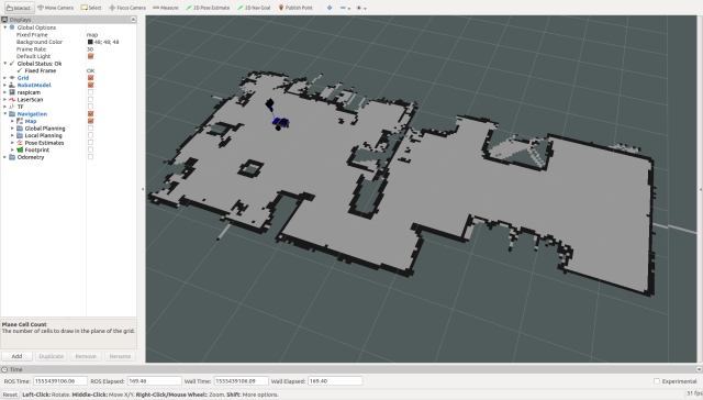
In order for our robot to navigate, it will need a map of its world. The node we are going to use to create the map will be run on a Linux workstation and will construct the map from data recorded from the robot sensors. You could run the node on the robot hardware. The ROS package is called gmapping and provides laser-based SLAM (Simultaneous Localization and Mapping). The following image shows a map created by gmapping from Rodney's sensors displayed in rviz.
The map is stored for later use in two files, a .yaml and a .pgm file. The .pgm file can be edited in a number of image editing tools so you can always tidy up the map and block off areas you may not wish your robot to visit.
You can create maps live but most tutorials will tell you to record the sensor data and then produce the map from the recorded data. This allows you to try different parameter settings when producing the map. I prefer a mixture of the two, record the data but also visualise the map in rviz as it is created. This allows you to ensure you have not missed parts of a map you really need.
You create the map by driving your robot slowly in manual mode. To improve the map quality as well as driving slowly, it is best to visit a location more than once. I'll show how to record the data and how to create and save the map in the "Using the Code" section.
Once we have a map, the robot will need access to the map and as usual with ROS, this is done using topics. The node providing these topics is part of the map_server package. Since the map may be large, the topic containing the map is not continually published, but is latched and any new nodes requiring the map will be passed a copy. As well as containing the map_server node, the package includes another node called map_saver which will be used to save the map created by gmapping to disk.
To launch the map_server node on the robot hardware, we will include the following in the rodney.launch file.
<arg name="map_file" default="second_floor"/>
<node pkg="map_server" type="map_server" name="map_server"
      args="$(find rodney)/maps/$(arg map_file).yaml" output="screen"/>
This implies that we will store our map files in a new folder in the rodney package called maps. If when we call the launch file, we don't provide a map_file parameter, the default value of second_floor will be used.
Robot Localisation
The next part of this navigation jigsaw puzzle we require is Robot Localisation. As well as keeping track of where it is in the world, the robot will also need to know its starting place. Now the odom and laser sensors are not perfect so the robot can't tell exactly where it is but will maintain an array of candidate poses of possible locations. A pose is a position and orientation in the world. As the robot moves and it narrows down where it thinks it is, it will discard the poses that are less likely to be its position.
For this functionality, we will use the amcl package. AMCL stands for Adaptive Monte Carlo Localization, luckily all we need to do is to configure it and launch it, if you wish to understand more about AMCL, then maybe this Wikipedia page is a good starting place.
As is normal with ROS, we will configure the node by loading some configuration data onto the parameter server. This data will be stored in the amcl_config.yaml file stored in the rodney/config folder. This is my version of the configuration file but as with all these navigation packages, they are highly configurable so consult the ROS Wiki for the package.
# Overall filter parameters
min_particles: 500
max_particles: 3000
kld_err: 0.05
kld_z: 0.99
update_min_d: 0.2
update_min_a: 0.5
resample_interval: 1
transform_tolerance: 0.5
recovery_alpha_slow: 0.0
recovery_alpha_fast: 0.0
gui_publish_rate: 1.0
# Laser model parameters
laser_max_beams: 30
laser_z_hit: 0.5
laser_z_short: 0.05
laser_z_max: 0.05
laser_z_rand: 0.5
laser_sigma_hit: 0.2
laser_lambda_short: 0.1
laser_likelihood_max_dist: 2.0
laser_model_type: likelihood_field
# Odometry model parameters
odom_model_type: diff
odom_alpha1: 0.2
odom_alpha2: 0.2
odom_alpha3: 0.8
odom_alpha4: 0.2
odom_alpha5: 0.1
odom_frame_id: odom
base_frame_id: base_footprint
To launch this node with the configuration given, we will add the following to the rodney.launch file.
<node pkg="amcl" type="amcl" name="amcl" output="screen">
  <rosparam command="load" file="$(find rodney)/config/amcl_config.yaml"/>
</node>
It's worth noting that most of the parameters I have changed from defaults are for the nav stack relate to transform tolerances and sample frequencies, we are asking the Raspberry Pi to do a lot of complex calculations in a short time here!
Planning a Route
Now we are getting to the business end of the process. If we want to get from point A to point B (or pose A to pose B) using the map, something needs to plan the route and command the robot to move. For this, we are going to use the move_base package. This package is going to have to use the amcl data, the map, the odom data and the laser data to plan the best route. Not only that, but it needs to allow for things that have changed since the map was constructed. If a person or a family pet walks into the path of the robot, it will need to come up with a new route. Again, to gain some understanding of this package, read its ROS Wiki page.
When planning the route, the package will use two costmaps. A costmap shows good and bad places for a robot to be. A good place is out in the open and a bad place would be against a wall. One costmap is the Global costmap and is based on the map and remains static. This map is used to plan the global route, but as said before what if things have changed from the map. This is where the Local costmap comes in. It's updated as the robot moves and whereas the Global costmap covers the entire map, the Local costmap covers only the immediate location around the robot.
The package move_base can use a number of global and local planners that are available as long as they adhere to the nav_core::BaseGlobalPlanner interface for global planning and nav_core::BaseLocalPlanner interface for local planning. So you can even write your own planners.
There are default planners you can use or you can declare which planners you are using in the configuration files. I'm going to use global_planner and dwa_local_planner.
We need a number of configuration files for the move_base package which will be loaded into the parameter server. Each file will be located in the rodney/config folder.
base_local_planner_params.yaml
controller_frequency: 5.0
use_grid_path: true
base_global_planner: global_planner/GlobalPlanner
base_local_planner: dwa_local_planner/DWAPlannerROS
DWAPlannerROS:
  acc_lim_x: 0.75
  acc_lim_y: 0.0
  acc_lim_theta: 1.75                 # wiki calls it acc_lim_th but it is acc_lim_theta
  acc_lim_trans: 1.0
  max_trans_vel: 0.25
  min_trans_vel: 0.1
  max_vel_x: 0.25                     # The maximum forward velocity
  min_vel_x: -0.1
  max_vel_y: 0.0
  min_vel_y: 0.0
  max_rot_vel: 2.5
  min_rot_vel: 0.3
  yaw_goal_tolerance: 0.3
  xy_goal_tolerance: 0.25
  sim_time: 2.0
  sim_granularity: 0.1
  vx_samples: 3
  vy_samples: 10
  vth_samples: 20
  path_distance_bias: 32.0
  goal_distance_bias: 24.0
  occdist_scale: 0.05
  forward_point_distance: 0.3
  stop_time_buffer: 0.5
  scaling_speed: 0.25
  max_scaling_factor: 0.2
  oscillation_reset_dist: 0.05
  prune_plan: true

  trans_stopped_vel: 0.1
  rot_stopped_vel: 0.1
  angular_sim_granularity: 0.1
  twirling_scale: 0.0
  oscillation_reset_angle: 0.2
  use_dwa: true
Here, we set the planners we are going to use and a large number of parameters for the local planner. Again, refer to the relevant Wiki for each parameter. Most of the parameters can be set dynamically using dynamic reconfiguration which we have used in the previous articles on Rodney. Values are also very particular to each robot and its environment. For example, at one point, I increased the maximum speed and rotational velocity thinking that it would be able to turn quicker around tight corners, but ended up with the robot getting stuck up against objects. It would appear that by going faster, the robot got itself into problem areas before it had time to calculate it was a bad area.
The costmaps have some common parameters between the global and local costmaps and some parameters which are particular to either the global or local costmap.
The common parameters are stored in the costmap_common_params.yaml file:
obstacle_range: 2.5
raytrace_range: 3.0
footprint: [[0.170, 0.145], [-0.170, 0.145],
           [-0.170, -0.145], [0.170, -0.145]] # Simple rectangle taking in the base and wheels
inflation_radius: 0.55
observation_sources: laser_scan_sensor
laser_scan_sensor:
  sensor_frame: laser
  data_type: LaserScan
  topic: scan
  marking: true
  clearing: true
For the footprint, I started with a complex shape which took into account the wheels sticking out from the base. But in order to make it less complex for the calculations, I changed it to a simple rectangle which included the base and the wheels.
The parameters that are particular to the global costmap are stored in the global_costmap_params.yaml file:
global_costmap:
  global_frame: map
  robot_base_frame: base_footprint
  static_map: true
  transform_tolerance: 0.5
  update_frequency: 1.0
Those that are particular to the local costmap are stored in the local_costmap_params.yaml file:
local_costmap:
  global_frame: odom
  robot_base_frame: base_footprint
  static_map: false
  rolling_window: true
  transform_tolerance: 0.5
  update_frequency: 1.0
  publish_frequency: 0.5
  width: 2.5
  height: 2.5
Again to help the calculations, I'm using a relatively small local costmap of 2.5x2.5 metres around the robot. Remember the local costmap is used to plan the route around objects that may have moved since the static map, which the global costmap is based on, was created. Increasing the width and height allows the robot to plan further ahead but at the expense of the number of calculations, the processor will need to carry out.
It's probably worth noting at this point that although I did have the navigation working on the Raspberry Pi 3B I have upgraded to a Raspberry Pi 3B+ to take advantage of the slightly faster processor.
To launch the move_base node and to load all the parameters, add the following to the rodney.lunch file:
<node pkg="move_base" type="move_base" name="move_base" respawn="false" output="screen">
  <rosparam command="load" file="$(find rodney)/config/base_local_planner_params.yaml"/>
  <rosparam command="load" file="$(find rodney)/config/costmap_common_params.yaml"
                           ns="global_costmap"/>
  <rosparam command="load" file="$(find rodney)/config/costmap_common_params.yaml"
                           ns="local_costmap"/>
  <rosparam command="load" file="$(find rodney)/config/global_costmap_params.yaml"/>
  <rosparam command="load" file="$(find rodney)/config/local_costmap_params.yaml"/>
  <remap from="cmd_vel" to="demand_vel"/>
</node>
The published topic from move_base is normally cmd_vel, which is the topic name which our thunderborg node subscribes to. Since we wish to be able to drive the robot manually, our rodney node was set up to publish on the cmd_vel topic, either data for manual driving or autonomous depending on the current mode of the robot. We therefore remap the topic name here from cmd_vel to demand_vel.
One other change I want to make to the rodney.launch file, is to be able to launch the software either with the nav stack enabled or not. The default will be to have the nav stack enabled but if we want to drive the robot remotely in order to produce a new map we don't want to run the map server and we don't want to launch the other nodes that will be looking for a map. I have therefore wrapped the sections for launching the various parts of the nav stack in "group unless" tags.
The complete rodney.launch file is reproduced below:
="1.0"
<launch>
<node pkg="rodney" type="static_broadcaster.py" name="static_broadcaster_node"/>
<rosparam command="load" file="$(find pan_tilt)/config/config.yaml"/>
<rosparam command="load" file="$(find face_recognition)/config/config.yaml"/>
<rosparam command="load" file="$(find head_control)/config/config.yaml"/>
<rosparam command="load" file="$(find rodney_missions)/config/config.yaml"/>
<arg name="no_nav" default="false"/>
<group unless="$(arg no_nav)">
<arg name="map_file" default="second_floor"/>
<node pkg="map_server" type="map_server" name="map_server"
args="$(find rodney)/maps/$(arg map_file).yaml" output="screen"/>
<node pkg="amcl" type="amcl" name="amcl" output="screen">
<rosparam command="load" file="$(find rodney)/config/amcl_config.yaml"/>
</node>
</group>
<include file="$(find raspicam_node)/launch/camerav2_1280x960.launch" />
<node pkg="pan_tilt" type="pan_tilt_node" name="pan_tilt_node"/>
<node pkg="face_recognition" type="face_recognition_node.py" name="face_recognition_node"/>
<node pkg="head_control" type="head_control_node" name="head_control_node"/>
<node pkg="speech" type="speech_node" name="speech_node"/>
<node pkg="rodney_missions" type="rodney_missions_node.py"
name="rodney_missions" output="screen"/>
<node pkg="rodney" type="rodney_node" name="rodney" output="screen">
<rosparam command="load" file="$(find rodney)/config/config.yaml"/>
</node>
<node pkg="thunderborg" type="thunderborg_node.py" name="thunderborg_node">
<rosparam command="load" file="$(find thunderborg)/config/config.yaml"/>
</node>
<arg name="serial_port" default="/dev/teensy"/>
<arg name="baud_rate" default="500000"/>
<node pkg="rosserial_python" type="serial_node.py" name="serial_node" output="screen">
<param name="port" value="$(arg serial_port)"/>
<param name="baud" value="$(arg baud_rate)"/>
</node>
<node pkg="rplidar_ros" type="rplidarNode" name="rplidar_node" output="screen">
<param name="serial_port" type="string" value="/dev/rplidar"/>
<param name="serial_baudrate" type="int" value="115200"/>
<param name="frame_id" type="string" value="laser"/>
<remap from="scan" to="scan_filter_input"/>
</node>
<node pkg ="laser_filters" type="scan_to_scan_filter_chain"
name="scan_to_scan_filter_chain" output="screen">
<rosparam command="load" file="$(find rodney)/config/laser_filter_config.yaml"/>
<remap from="scan" to="scan_filter_input"/>
<remap from="scan_filtered" to="scan"/>
</node>
<node pkg="homer_robot_face" type="RobotFace" name="RobotFace"/>
<node pkg="imu_calib" type="apply_calib" name="imu_calib" output="screen">
<param name="calib_file" value="$(find rodney)/config/imu_calib.yaml"/>
</node>
<node pkg="robot_localization" type="ekf_localization_node" name="ekf_localization_node">
<remap from="odometry/filtered" to="odom"/>
<rosparam command="load" file="$(find rodney)/config/robot_localization.yaml"/>
</node>
<group unless="$(arg no_nav)">
<node pkg="move_base" type="move_base"
name="move_base" respawn="false" output="screen">
<rosparam command="load" file="$(find rodney)/config/base_local_planner_params.yaml"/>
<rosparam command="load"
file="$(find rodney)/config/costmap_common_params.yaml" ns="global_costmap"/>
<rosparam command="load"
file="$(find rodney)/config/costmap_common_params.yaml" ns="local_costmap"/>
<rosparam command="load" file="$(find rodney)/config/global_costmap_params.yaml"/>
<rosparam command="load" file="$(find rodney)/config/local_costmap_params.yaml"/>
<remap from="cmd_vel" to="demand_vel"/>
</node>
</group>
</launch>
In the next article, we will be changing the rodney_missions node to programmatically run autonomous navigation and combine it with the face recognition functionality to wander through the house searching for a known person to deliver the message to.
In the "Using the Code" section, we will create a map and use rviz to input poses which the robot will autonomously navigate to.
Robot Hardware
A full size image of the current circuit diagram is available in the diagrams zip folder along with a full size copy of the image from rqt_graph showing all the nodes and topics.
A complete bill of material for the project so far is available here.
In part 1 of the article, I referenced the Ubiquity Robot Image which I use on the Raspberry Pi. Instructions on how to install the image, install extra software and configure it for the project are available here.
As usual, I'll run the code on the robot hardware and run the test tools and manual control nodes on a Linux PC. I'll refer to this PC as the workstation in the details below.
Building the ROS Packages on the Pi (Robot Hardware)
If not already done, create a catkin workspace on the Raspberry Pi and initialise it with the following commands:
$ mkdir -p ~/rodney_ws/src
$ cd ~/rodney_ws/
$ catkin_make
Copy the packages face_recognition, face_recognition_msgs, head_control, imu_calib, pan_tilt, rodney, rodney_missions, ros-keyboard, rplidar-ros, servo_msgs, speech, tacho_msgs and thunderborg into the ~/rodney_ws/src folder.
Build the code with the following commands:
$ cd ~/rodney_ws/
$ catkin_make
Check that the build completes without any errors.
You will also need to compile and download the sketch to the Teensy 3.5.
Building the ROS Packages on the Workstation
On the workstation, we want to run the keyboard, joystick and heartbeat nodes so that we can control the actual robot hardware remotely.
Create a workspace with the following commands:
$ mkdir -p ~/test_ws/src
$ cd ~/test_ws/
$ catkin_make
Copy the packages rodney, joystick, and ros-keyboard into the ~/test_ws/src folder, and then build the code with the following commands:
$ cd ~/test_ws/
$ catkin_make
Check that the build completes without any errors.
Tip
When running ROS code and tools on a workstation and the Raspberry Pi, there can be a lot of repeat typing of commands at a number of terminals. In the next sections, I have included the full commands to type but here are a few tips that can save you all that typing.
On the Raspberry Pi, to save typing "source devel/setup.bash", I have added it to the .bashrc file for the Raspberry Pi.
$ cd ~/
$ nano .bashrc
Then add "source /home/ubuntu/rodney_ws/devel/setup.bash" to the end of the file, save and exit.
When running test code and tools on the workstation, it also needs to know where the ROS master is so I have added the following to the .bashrc file for the workstation.
alias rodney='source ~/test_ws/devel/setup.bash; \
export ROS_MASTER_URI=http://ubiquityrobot:11311'
Then, by just typing "rodney" at a terminal, the two commands are run and a lot of typing is saved.
You can also save some typing as some ROS tools support TAB completion. For example, type rosrun rosserial_ and then press the tab key to auto complete rosrun rosserial_python.
Watching the Log File
As the robot navigates around, you may like to keep an eye on log messages. These will be displayed in the terminal that you use to launch the code from but that's not helpful if the robot is moving and in a different room. You can view the log at the workstation with the following commands:
$ export ROS_MASTER_URI=http://ubiquityrobot:11311
$ rqt_console

Creating a Map
On the robot hardware, run the following commands to start all the current nodes in the system with the exception of the navigation stack:
$ source rodney_ws/devel/setup.bash
$ roslaunch rodney rodney.launch no_nav:=True
On the workstation, run the following commands to start the remote control nodes:
$ source test_ws/devel/setup.bash
$ export ROS_MASTER_URI=http://ubiquityrobot:11311
$ roslaunch rodney remote.launch
A small window whose title is "ROS keyboard input" should be running. When entering keyboard strokes, ensure the small window has the focus.
Next, we will start recording the transforms and laser scan messages so that we can show how to create a map from recorded data. In a terminal, start the recording with the following commands:
$ export ROS_MASTER_URI=http://ubiquityrobot:11311
$ rosbag record -O data.bag /scan /tf
Here, we are going to start slam_gmapping so that we can see a live map being created. I'll also limit the size of the map. In a terminal on the workstation, run the following commands:
$ export ROS_MASTER_URI=http://ubiquityrobot:11311
$ rosparam set slam_gmapping/xmax 10
$ rosparam set slam_gmapping/ymax 10
$ rosparam set slam_gmapping/xmin -10
$ rosparam set slam_gmapping/ymin -10
$ rosparam set slam_gmapping/delta 0.05
$ rosrun gmapping slam_gmapping
As an alternative, I have created a test package called mapping_launch that contains a launch file called mapping.launch which will set the parameters and start gmapping. This package is available in the Robotics-test-code folder.
In another terminal on the workstation, start rviz with the following commands:
$ source test_ws/devel/setup.bash
$ export ROS_MASTER_URI=http://ubiquityrobot:11311
$ roslaunch rodney rviz.launch
Configure rviz so that:
- The fixed frame is map
- LaserScan is displaying the /scan topic
- TF is displaying the base_link
- Map is displaying the /map topic
Using the joystick and/or keyboard, enter manual mode, ensure the LIDAR motor is running and manually drive the robot around its world. Go slow and visit each location at least twice. The map being created should be visible on rviz.
Once you have created the map, press Ctrl-C in the terminal running rosbag to finish storing the messages.
We can now save the map that is visible in rviz, to disk. With slam_gmapping still running, enter the following command in the terminal that was running rosbag:
$ rosrun map_server map_saver -f my_first_map
This will result in two files been saved, my_first_map.yaml and my_first_map.pgm
You can at this point if you wish regenerate the map from the rosbag file with different gmapping parameters. Here, we don't want any of the existing nodes running on the workstation so shutdown and close all the terminals. You can also shutdown the robot.
At the workstation, we need a ROS master running (in the previous setup, this was running automatically on the robot hardware), enter the following in a terminal:
$ roscore
In another terminal, use rosparam to set the required gmapping parameters and then type the following:
$ rosparam set use_sim_time_true
$ rosrun gmapping slam_gmapping
In another terminal, playback the rosbag fle recorded previously with the following command:
$ rosbag play --clock data.bag
Then, sit back while gmapping creates the map. If you wish, you could start rviz (without the export ROS_MASTER_URI command) and watch the map being created. Once all the messages have been played back, store the new map to disk with the following command:
$ rosrun map_server map_saver -f my_second_map
You can play with the gmapping configuration parameters here as much as you like and keep playing back the recoded bag file to see the differences the parameters have on the generated map.
Autonomous Navigation
Now the bit we have all been waiting for, autonomous navigation.
On the robot hardware, run the following commands to start all the current nodes in the system including the navigation stack. I'm going to use my default map but you can set the map by adding "map_file:=my_first_map" to the end of the roslaunch command.
$ source rodney_ws/devel/setup.bash
$ roslaunch rodney rodney.launch
On the workstation, run the following commands to start the remote control node:
$ source test_ws/devel/setup.bash
$ export ROS_MASTER_URI=http://ubiquityrobot:11311
$ roslaunch rodney remote.launch
A small window whose title is "ROS keyboard input" should be running. When entering keyboard strokes, ensure the small window has the focus.
In another terminal on the workstation, start rviz with the following commands:
$ source test_ws/devel/setup.bash
$ export ROS_MASTER_URI=http://ubiquityrobot:11311
$ roslaunch rodney rviz.launch
Localising the Robot
Configure rviz to display the robot model or base_link axis, laser scan, map and pose estimates. Also ensure that the map is the fixed frame.
We can see from the display that the laser scan does not match the map, the pose estimates are spread around. So before we give the robot a navigational goal, we need to improve its localisation.
The image below shows a poorly localised robot. The red lines are the laser scan and the green arrows are the pose estimates.
The first operation we will carry out is to give the robot an improved localisation using rviz. Click the "2D Pose Estimate" button, estimate the real location and pose of the robot and click/drag the large green arrow on the map to set the initial pose. You can keep doing this until you get the laser scan close to matching the map.
We now have a good initial pose but the pose estimates are still out. We can improve these by driving the robot around in manual mode. Spinning on the spot is a good manoeuvre to conduct. Whilst moving the robot, you should see the pose estimates converging on the robots position.
Setting a Navigation Goal
We are now ready to send the robot on its way but let’s first take a look at the costmaps that will be used for planning the route. Select Global Planning in rviz to display the Global Costmap. For the Global Costmap, I like to select "Draw Behind" so that the map is washed out behind the main map.
From the costmap, you can see the open spaces the planner will try and use and the risker places like up against a wall.
Now the Global Costmap was constructed from the main map and will be used to plan an ideal route, but the actual movement of the robot will be governed by the Local Costmap and this will be generated on the fly as the sensor data arrives. This will allow the robot to avoid objects that weren't there when the map was created, i.e., a sleeping family pet.
Select Local Planning in rviz to display the Local Costmap. I like to have this map superimposed on top of the main map.
Now set the target goal pose by clicking the "2D Nav Goal" button, click/drag the large green arrow on the map to set the goal. Now I have deliberately left the robot in manual mode so it will not move and this gives us a chance to examine the global plan which is shown as a thin green line in the image below.
We can put the robot into an autonomous mode by giving the ROS keyboard input window the focus and pressing the "1" key (not on the numeric keypad). This is the request to run mission 1 which is currently empty so all it does is take the robot out of manual mode so that the velocities generated by the navigation stack and not the joystick/keyboard will be sent to the thundeborg node which controls the motors.
Hopefully, the robot will navigate to the goal pose and you can monitor the progress on rviz. In the image below, the robot has arrived at the goal.
I have noticed that after setting a number of poses to move to, eventually despite the clear route on the costmaps, the nav stack fails to calculate a route. You can clear this problem with the following command at the workstation:
$ rosservice call /move_base/clear_costmaps
Points of Interest
In this part, we have added autonomous navigation.
In the next article, we will programmatically set navigation goals and include the face recognition functionality in a mission so that Rodney can wander around the house looking for the person who he should deliver the message to.
Whilst I include the current version of all the code under development in the source zip file, the code is also available at my GitHub Site. Each package is in its own repository. Please feel free to Fork the repositories for your own projects make updates and if you feel any changes will be helpful to myself or others, then create a Pull Request.
History
- 2019/04/23: Initial release
Having spent the last 40 years as an engineer, 19 years as a test and commissioning engineer and 21 years as a software engineer, I have now retired to walk the Cumbrian fells and paddle the coast and lakes. When the weather is inclement I keep my hand in with robotic software and hardware. Over the years I have used Code Project to help me solve some programming issues so now with time on my hands it’s time to put something back into the Code Project.


