
Rodney - A Long Time Coming Autonomous Robot (Part 5)
5.00/5 (11 votes)
Fifth part in a series on a ROS (Robot Operating System) House Bot
Introduction
The Rodney Robot project is a hobbyist robotic project to design and build an autonomous house-bot using ROS (Robot Operating System). This article is the fifth in the series describing the project.
Background
In part 1, to help define the requirements for our robot, we selected our first mission and split it down into a number of Design Goals to make it more manageable.
The mission was taken from the article, Let's build a robot! and was: Take a message to... - Since the robot will [have] the ability to recognize family members, how about the ability to make it the 'message taker and reminder'. I could say 'Robot, remind (PersonName) to pick me up from the station at 6pm'. Then, even if that household member had their phone turned on silent, or were listening to loud music or (insert reason to NOT pick me up at the station), the robot could wander through the house, find the person, and give them the message.
The design goals for this mission were:
- Design Goal 1: To be able to look around using the camera, search for faces, attempt to identify any people seen and display a message for any identified
- Design Goal 2: Facial expressions and speech synthesis. Rodney will need to be able to deliver the message
- Design Goal 3: Locomotion controlled by a remote keyboard and/or joystick
- Design Goal 4: Addition of a laser ranger finder or similar ranging sensor used to aid navigation
- Design Goal 5: Autonomous locomotion
- Design Goal 6: Task assignment and completion notification
In the previous parts of the article, we completed Design Goal 1 and 2, we also added control of the missions and started on Design Goal 3. In this part, I'm going to add the electric motors, a motor control board and the software to drive the control board. That will complete Design Goal 3 and I'll also briefly discuss the hardware build of the robot so far.
2WD vs 4WD
When I first started working on Rodney, he was going to have four wheels and be steered using what is called "Skid steering". Skid steering is good for rough terrain but requires high power usage when turning. I also found in my initial experiments that the turning was a little unpredictable, this may have been due to the wide knobbly tyres I was using gripping the floor carpet. Now Rodney was always intended to be a house bot and not required to roam around Mars so manoeuvring over rough terrain is not a requirement, therefore I changed the design to be two wheels and two passive casters. This type of drive is known as "Differential drive". Differential drive is easier to design, but not good for driving over bumps and obstacles.
For the casters, I originally tried two furniture swivel casters but found they didn't always line up in the direction of travel causing the robot to move off course. I then came across a 3D print on the Thingiverse website which uses a table tennis ball for a caster. I added my own 3D printed spacer to get the required height. It doesn't have rollers inside which you would get with a commercial ball caster, but it does seem to work OK.

Motor Control Board
The next design decision was what to use as a control board to power the electric motors. In the first article in the series, I referenced another robot project, PiRex – remote controlled Raspberry Pi based robot, which used a simple L293D chip. I also considered using an L298N motor driver board but in the end, chose the much more sophisticated Thunderborg from the PiBorg company. Although more expensive than the other boards, this board is higher powered, includes under voltage and short circuit protection, you can read the battery voltage and you can enable it in such a way that if our software stops talking to the board, it will shut the motors down and thus stop a runaway robot. The board includes a 5V regulator and we will use this supply to power the Raspberry Pi.
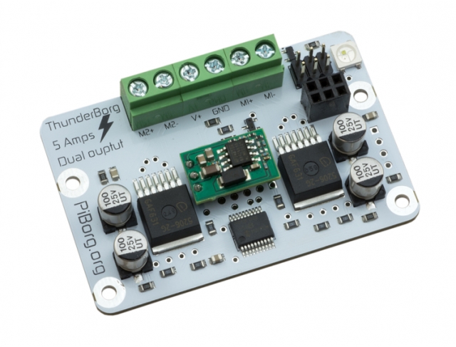
Communication with the board is over an I2C link and you can copy a library from the PiBorg website which takes care of the communication between the Raspberry Pi and a Thunderborg. This means that all you need to do to control a motor is to call functions like TB.SetMotor1(0.5)
This zip file from the PiBorg website includes example code and the library file I'll be using within my ROS node.
Geared Motor with Encoder
For the two electric motors, I'm going to use 12V geared motors which include a Hall effect sensor. We will use a PID controller to control the motor speed of each wheel and although the feedback from the Hall sensor is important for the PID functionality, the main use of the sensor will be to generate an odometry message which will eventually be used along with the LIDAR data by the ROS navigation system when in autonomous mode.

Code
Turning our attention to the code, we will write two new ROS packages and update the rodney package mainly by updating the Arduino sketch to process the signals from the Hall sensors.
tacho_msgs Package
The first of the new packages is quite simple as it just contains a ROS user defined message which will be used to send the left and right motor RPM from the node running on the Arduino to our node controlling the motors which will be running on the Raspberry Pi.
The files that make up this first package are available in the tacho_msgs folder. The root folder contains all the usual files that go to make up a ROS package.
The msg folder within the package contains the definition file for our message, tacho.msg:
float32 lwheelrpm   # RPM of the left wheel
float32 rwheelrpm   # RPM of the right wheel
The lwheelrpm element will contain the RPM value of the left hand motor and the rwheelrpm element the RPM value of the right hand motor.
The package also includes the test.launch file in the launch folder. This file simply launches the serial node which communicates with the Arduino and was used in the early testing of the package.
That completes our first new ROS package.
thunderborg Node Package
The next package will form a node that is used as a driver for the Thunderborg controller and also produces raw odometry messages. Our ROS package for the node is called thunderborg and is available in the thunderborg folder. The package contains all the usual ROS files.
The cfg folder contains the file thunderborg.cfg. This file is used by the dynamic reconfiguration server so that we can adjust the PID parameters on the fly. As you can see, the file is actually a Python script.
#!/usr/bin/env python
# Dynamic rconfiguration for Thunderborg node
PACKAGE = "thunderborg"

from dynamic_reconfigure.parameter_generator_catkin import *

gen = ParameterGenerator()

gen.add("p_param", double_t, 0, "P-Proportional", 0.5, 0, 5)
gen.add("i_param", double_t, 0, "I-Integral", 0.9, 0, 5)
gen.add("d_param", double_t, 0, "D-Derivative", 0.006, 0, 5)

gen.add("restore_defaults", bool_t, 0, "Restore to original configuration", False)

exit(gen.generate(PACKAGE, "thunderborg_node", "Thunderborg"))
We have used the dynamic reconfiguration server in the previous parts of the article. Here, the default parameters for the PID will be 0.5 for the proportional parameter, 0.9 for the integral parameter and 0.006 for the derivative parameter. You will be able to tune the PID controller using the rqt_reconfiguration application. Once you have found the optimum values, update them in the config.yaml file shown below.
Note that although default values are set in the thunderborg.cfg file the values will be set from the parameters of the same name given in the next file.
The config folder contains the file config.yaml. This file will be used by the launch file to set the given parameters in the parameter server. This will allow us to configure the system without having to recompile the code.
p_param: 0.5
i_param: 0.9
d_param: 0.006

pid:
  use_pid: true
  inertia_level: 0.1

wheels:
  distance: 0.242
  circumference: 0.317

speed:
  # Plot x=thunderborg value, y=m/s
  slope: 0.649776
  y_intercept: -0.0788956
  motor_diag_msg: false
The parameters are as follows:
p_parmthe proportional parameter for the PID controlleri_parmthe integral parameter for the PID controllerd_parmthe derivative parameter for the PID controllerpid/use_pidif set totrue, the PID controller will be used to control the speed of the motorspid/inertia_levelidentifies a motor speed value at and below which the robot will not movewheels/distanceis the distance in metres between the two wheelswheels/circumferenceis the circumference of the wheels in metresspeed/slopeis the slope value of the graph used to convert velocity in metres/second into a value the motor controller usesspeed/y_interceptis the y-intercept value of the graph described abovespeed/motor_diag_msgif set totrue, the system publishes a diagnostic message for each motor which can be used in testing
The code for the ROS node itself is in the sub folder src in the file thunderborg_node.py. The code makes use of a library file, ThunderBorg.py, which contains the code from the PiBorg website and is in the sub folder src/thunderborg_lib. As the library is written in Python, we will write our node in Python also.
Next, I'll describe the ROS node itself.
The main routine initialises ROS for the node and creates an instance of ThunderBorgNode and then enters a loop until the node is shutdown. This loop runs at 20Hz and calls several functions of the ThunderBorgNode which will be described below. PublishStatus will be called at a 1Hz rate where as PublishOdom and RunPIDs are called on each iteration of the 20Hz loop.
def main(args):
    rospy.init_node('thunderborg_node', anonymous=False)
    rospy.loginfo("Thunderborg node started")
    tbn = ThunderBorgNode()

    rate = rospy.Rate(RATE)

    status_time = rospy.Time.now()

    while not rospy.is_shutdown():

        if rospy.Time.now() > status_time:
            tbn.PublishStatus()
            status_time = rospy.Time.now() + rospy.Duration(1)

        # Publish ODOM data
        tbn.PublishOdom()

        # Run the PIDs
        tbn.RunPIDs()

        rate.sleep()


if __name__ == '__main__':
    main(sys.argv)
The rest of the file contains the ThunderBorgNode class.
The constructor for ThunderBorgNode reads the values from the parameter server. If any of the parameters are not loaded in the server, then the default values are used.
If the /pid/use_pid parameter is set to true, then two instances of the PID, one from each motor, are created. The PID code we are going to use is the simple-pid library.
The constructor then creates an instance of the class used to communicate with the Thunderborg board and then checks that the board communicates on the set I2C address.
A number of variables are then initialised which include the topics that the node will publish on and subscribe to.
The node will publish the battery status on the topic main_battery_status, the odometry data on the raw_odom topic and if enabled the motor 1 and 2 diagnostic messages on the motor1_diag and motor2_diag topics.
The topics that the node subscribes to are the cmd_vel topic which is published by the rodney node from part 4 and gives the required velocities of the robot and the tacho topic which will give the RPM of each motor.
class ThunderBorgNode:
    def __init__(self):
        self.__setup = False
        # Read values from parameter server
        # Using '~private_name' will prefix the parameters with the node name given in launch file
        self.__use_pid = rospy.get_param('~pid/use_pid', False)
        self.__wheel_distance = rospy.get_param('~wheels/distance', 0.23)
        self.__wheel_circumference = rospy.get_param('~wheels/circumference', 0.34)
        self.__speed_slope = rospy.get_param('~speed/slope', 1.5)
        self.__speed_y_intercept = rospy.get_param('~speed/y_intercept', 0.4)
        self.__inertia = rospy.get_param('~pid/inertia_level', 0.0)
        self.__diag_msgs = rospy.get_param('~speed/motor_diag_msg', False)

        pid_p = rospy.get_param('~p_param', 0.0)
        pid_i = rospy.get_param('~i_param', 0.0)
        pid_d = rospy.get_param('~d_param', 0.0)

        if self.__use_pid == True:
            # Configure the PIDs.
            self.__pid1 = PID(pid_p, pid_i, pid_d, setpoint=0)
            self.__pid1.sample_time = 0.05
            # Limit the pid range. The PID will only work in positive values
            self.__pid1.output_limits = (self.__inertia, 1.0)

            self.__pid2 = PID(pid_p, pid_i, pid_d, setpoint=0)
            self.__pid2.sample_time = 0.05
            self.__pid2.output_limits = (self.__inertia, 1.0)

            # We call dynamic server here after the PIDs are set up
            # so the new PID values are set after the PIDs were created
            srv = Server(ThunderborgConfig, self.DynamicCallback)

        self.__thunderborg = thunderborg_lib.ThunderBorg()  # create the thunderborg object
        self.__thunderborg.Init()
        if not self.__thunderborg.foundChip:
            rospy.logdebug("ThunderBorg board not found")
        else:
            # Setup board to turn off motors if we don't send a message every 1/4 second
            self.__thunderborg.SetCommsFailsafe(True)

        # Motor velocity feedback values m/s
        self.__feedback_velocity_right = 0.0
        self.__feedback_velocity_left = 0.0

        # Last motor direction
        self.__fwd_right = True
        self.__fwd_left = True

        # Speed request in m/s
        self.__speed_wish_right = 0.0
        self.__speed_wish_left = 0.0

        # Publish topics
        self.__status_pub = rospy.Publisher("main_battery_status", BatteryState, queue_size=1)
        self.__odom_pub = rospy.Publisher("raw_odom", Odometry, queue_size=50)
        if self.__diag_msgs == True:
            self.__diag1_pub = rospy.Publisher("motor1_diag", Vector3, queue_size=1)
            self.__diag2_pub = rospy.Publisher("motor2_diag", Vector3, queue_size=1)

        # ODOM values
        self.__odom_x = 0.0
        self.__odom_y = 0.0
        self.__odom_th = 0.0
        self.__last_odom_time = rospy.Time.now()

        # Subscribe to topics
        self.__vel_sub = rospy.Subscriber("cmd_vel",Twist, self.VelCallback)
        self.__feedback_sub = rospy.Subscriber("tacho", tacho, self.TachoCallback)
The function DynamicCallback is called during initialisation and when the PID parameters are changed. The main purpose of this function is to set the PID parameters for the two PID controllers to the new values during dynamic reconfiguration.
The first time the function is called the configuration is saved as the default value. This default setup can be returned to by clicking the "Restore to original configuration" box on the reconfiguration server.
    # Dynamic recofiguration of the PIDS
    def DynamicCallback(self, config, level):
        # First time called just store the configuration
        if self.__setup == False:
            self.__default_config = config
            self.__setup = True
        else:
            # Check to restore config
            if config.restore_defaults == True:
                config = self.__default_config
                config.restore_defaults = False

            self.__pid1.tunings = (config.p_param, config.i_param, config.d_param)
            self.__pid2.tunings = (config.p_param, config.i_param, config.d_param)

        return config
The function MotorSetting is a helper function used to convert a required motor velocity from metres/second to a value used by the Thunderborg board. The Thunderborg uses values from 0.0 to 1.0 to control the motor speed. For example, a value of 0.5 will set the motor speed to half of its maximum speed. This function uses a straight line graph described by the slope and y-intercept values given in the config file to calculate the motor values. How to calculate the values for the slope and y-intercept are given later in the article.
    # Function to calculate thunderborg setting from velocity
    def MotorSetting(self, vel):
        if vel == 0.0:
            setting = 0.0
        else:
            setting = (abs(vel)-self.__speed_y_intercept)/self.__speed_slope
            if vel < 0.0:
                setting = -(setting)
        return setting
The function VelCallback is called each time a message on the cmd_vel topic is received. From the velocities given in the cmd_vel message, that's the linear x and angular z velocities, a required speed for both the right and left motors is calculated, these are the speed wish right and left values.
The helper function MotorSetting is then called twice, once per motor, to calculate the values that should be passed to the Thunderborg board to obtain these speeds.
These motor values are then used in two different ways depending on if the PID controller is being used or not.
If the PID controller is enabled, the absolute value is used to set the relative PID controllers set point. The set point is the value that the PID controller is moving to. Note that we use absolute values as to keep things simple with the PID controller. We will add the sign back in later to control the actual direction of the motor.
If the PID controller is not enabled, then we call the thunderborg library directly to set the required motor speed. If the publication of the diagnostic message is enabled, we will also publish a message for each motor. The message contains the required speed in m/s, the current feedback velocity for each motor in m/s and the actual motor value passed to the Thunderborg board.
    # Callback for cmd_vel message
    def VelCallback(self, msg):
        # Calculate the requested speed of each wheel
        self.__speed_wish_right = ((msg.angular.z * self.__wheel_distance) / 2) + msg.linear.x
        self.__speed_wish_left = (msg.linear.x * 2) - self.__speed_wish_right

        # Convert speed demands to values understood by the Thunderborg.
        motor1_value = self.MotorSetting(self.__speed_wish_right)
        motor2_value = self.MotorSetting(self.__speed_wish_left)

        if self.__use_pid == True:
            # Using the PID so update set points
            self.__pid1.setpoint = abs(motor1_value)
            self.__pid2.setpoint = abs(motor2_value)

            if motor1_value == 0.0:
                # Leave flag as is
                pass
            elif motor1_value < 0.0:
                self.__fwd_right = False
            else:
                self.__fwd_right = True

            if motor2_value == 0.0:
                # Leave flag as is
                pass
            elif motor2_value < 0.0:
                self.__fwd_left = False
            else:
                self.__fwd_left = True

        else:
            # Update the Thunderborg directly
            self.__thunderborg.SetMotor1(motor1_value)
            self.__thunderborg.SetMotor2(motor2_value)

            if self.__diag_msgs == True:
                motor1_state = Vector3()
                motor1_state.x = self.__speed_wish_right
                motor1_state.y = self.__feedback_velocity_right
                motor1_state.z = motor1_value
                motor2_state = Vector3()
                motor2_state.x = self.__speed_wish_left
                motor2_state.y = self.__feedback_velocity_left
                motor2_state.z = motor2_value
                self.__diag1_pub.publish(motor1_state)
                self.__diag2_pub.publish(motor2_state)
The function TachoCallback is called each time a message on the tacho topic is received. This message contains the RPM of each motor and the function converts the values to m/s and stores them for later use.
    # Callback for tacho message
    def TachoCallback(self, msg):
        # Store the feedback values as velocity m/s
        self.__feedback_velocity_right = (msg.rwheelrpm/60.0)*self.__wheel_circumfrence
        self.__feedback_velocity_left = (msg.lwheelrpm/60.0)*self.__wheel_circumfrence
The function PublishStatus is called once a second from the main loop. It creates an instance of the BatteryState message, reads the current battery value from the Thunderborg board and populates the voltage element of the message with the returned value. It then publishes the message on the main_battery_status topic. This topic was discussed in part 4 of this article.
    # Publish the battery status
    def PublishStatus(self):
        battery_state = BatteryState()
        # Read the battery voltage
        try:
            battery_state.voltage = self.__thunderborg.GetBatteryReading()
            self.__status_pub.publish(battery_state)
        except:
            rospy.logwarn("Thunderborg node: Failed to read battery voltage");
The function RunPIDs is called each time around the main loop. It basically passes the current feedback value to the PID controller and in return is given the current value as the PID moves to the set point. We then add back in the sign to this value and make the call to set the motor speeds for the Thunderborg board. If the diagnostic message is enabled, we publish the diagnostic messages for each motor, this time, the values in the message are the set point value, the output from the PID controller and the current feedback from the motor.
    # Update the PIDs and set the motor speeds
    def RunPIDs(self):
        if self.__use_pid == True:
            # Update PIDs and get next value.
            if abs(self.__feedback_velocity_right) <= self.__inertia:
                pid1_output = self.__pid1(self.__inertia)
            else:
                pid1_output = self.__pid1(self.MotorSetting(abs(self.__feedback_velocity_right)))

            if abs(self.__feedback_velocity_left) <= self.__inertia:
                pid2_output = self.__pid2(self.__inertia)
            else:
                pid2_output = self.__pid2(self.MotorSetting(abs(self.__feedback_velocity_left)))

            if pid1_output <= self.__inertia:
                motor1_speed = 0.0
            elif self.__fwd_right == False:
                motor1_speed = -(pid1_output)
            else:
                motor1_speed = pid1_output

            if pid2_output <= self.__inertia:
                motor2_speed = 0.0
            elif self.__fwd_left == False:
                motor2_speed = -(pid2_output)
            else:
                motor2_speed = pid2_output

            # Set motor value
            self.__thunderborg.SetMotor1(motor1_speed)
            self.__thunderborg.SetMotor2(motor2_speed)

            if self.__diag_msgs == True:
                motor1_state = Vector3()
                motor1_state.x = self.__pid1.setpoint
                motor1_state.y = pid1_output
                motor1_state.z = self.__feedback_velocity_right
                motor2_state = Vector3()
                motor2_state.x = self.__pid2.setpoint
                motor2_state.y = pid2_output
                motor2_state.z = self.__feedback_velocity_left
                self.__diag1_pub.publish(motor1_state)
                self.__diag2_pub.publish(motor2_state)
The final function in this class is the PublishOdom function. This function is also called each time around the main loop. From the velocity feedback value for each motor, it calculates the current forward and angular velocities. From these velocities and with the time elapsed since the last call, we calculate the distance moved in the x direction and the rotation around z since the last call. These values are then added to the odometry values. The rotation is required to be in Quaternion form so we use a helper function from the ROS transform package to carry out the conversion. The function then creates an Odometry message which it populates with the odometry data and the current velocities. This message is then published on the raw_odom topic. This topic will be used to produce an odom topic which will be used by the ROS navigation system when we use the robot in manual mode to map a location, and again in autonomous mode to navigate the same location. Of course, we will also need data from a LIDAR (light detection and ranging) for these navigational functions which we will look at in the next article.
How we are going to use the raw odometry data to produce the odometry data used by the navigation system is covered later in this article.
# Publish odometry data
    def PublishOdom(self):
        forward_velocity = (self.__feedback_velocity_left + self.__feedback_velocity_right)/2
        angular_velocity = 2*(self.__feedback_velocity_right - forward_velocity)/self.__wheel_distance

        # Now the x and y velocities
        velocity_x = forward_velocity
        velocity_y = 0.0

        # Note: As we don't receive velocity y we could remove all reference to it below, but
        # setting it to zero means we can keep the code generic below for future reference

        # Compute odometry from the calculate velocities
        current_time = rospy.Time.now()
        delta_time = (current_time - self.__last_odom_time).to_sec()    # Floating point seconds
        delta_x = (velocity_x * cos(self.__odom_th) - velocity_y * sin(self.__odom_th)) * delta_time
        delta_y = (velocity_x * sin(self.__odom_th) + velocity_y * cos(self.__odom_th)) * delta_time
        delta_th = angular_velocity * delta_time

        # Add the latest calculated movement
        self.__odom_x += delta_x
        self.__odom_y += delta_y
        self.__odom_th += delta_th

        # we need Yaw in a Quaternion
        odom_quat = quaternion_from_euler(0, 0, self.__odom_th)

        # Next publish the odometry message over ROS
        odom = Odometry()
        odom.header.stamp = current_time
        odom.header.frame_id = 'odom'

        odom.child_frame_id = 'base_footprint'

        odom.pose.pose = Pose(Point(self.__odom_x, self.__odom_y, 0.0), Quaternion(*odom_quat))
        odom.pose.covariance = [0.001, 0.0, 0.0, 0.0, 0.0, 0.0,
                                0.0, 0.001, 0.0, 0.0, 0.0, 0.0,
                                0.0, 0.0, 0.0, 0.0, 0.0, 0.0,
                                0.0, 0.0, 0.0, 0.0, 0.0, 0.0,
                                0.0, 0.0, 0.0, 0.0, 0.0, 0.0,
                                0.0, 0.0, 0.0, 0.0, 0.0, 0.001]

        odom.twist.twist = Twist(Vector3(velocity_x, velocity_y, 0), Vector3(0, 0, angular_velocity))

        odom.twist.covariance = [0.0001, 0.0, 0.0, 0.0, 0.0, 0.0,
                                 0.0, 0.0001, 0.0, 0.0, 0.0, 0.0,
                                 0.0, 0.0, 0.0, 0.0, 0.0, 0.0,
                                 0.0, 0.0, 0.0, 0.0, 0.0, 0.0,
                                 0.0, 0.0, 0.0, 0.0, 0.0, 0.0,
                                 0.0, 0.0, 0.0, 0.0, 0.0, 0.0001]

        # Publish the message
        self.__odom_pub.publish(odom)

        self.__last_odom_time = current_time
Within the src folder, there is also a non ROS Python script, test.py, which we will use in a test to calculate the slope and y-intercept of the graph used to convert wheel velocity to motor speed settings. The use of this file is explained later in this article.
#!/usr/bin/env python
import thunderborg_lib
import time

# Run with different values 0.1, 0.2, 0.3, 0.4, 0.5, 0.6, 0.7, 0.8, 0.9, 1.0
# WARNING ensure your robot has room to run for 5 seconds at the set speed or change the sleep time!
speed = 0.5

TB = thunderborg_lib.ThunderBorg()  # create the thunderborg object
TB.Init()

if not TB.foundChip:
    print("ThunderBorg board not found")
else:
    # Set both motor speeds
    TB.SetMotor1(speed)
    TB.SetMotor2(speed)

    time.sleep(5)

    TB.SetMotor1(0.0)
    TB.SetMotor2(0.0)
Fusing Odometry Data
The odometry data is only an estimate of position and pose and will drift with time. We can improve it by fusing the raw odometry data with data from an IMU (Inertial Measurement Unit) using a Kalman Extended Filter. Now I’m not going to add the IMU here, that’s for the future, but I’ll include a ROS Kalman Extended Filter node and we will be IMU ready. The node will ignore the fact that it’s not receiving IMU data and will publish odom data. It will also broadcast the odom transformation data. More information on transforms is available on the ROS Wiki.
The package we will use is the robot_localization package and documentation for it can be found here.
In the rodney/config folder I have add a robot_localization.yaml configuration file for the node. It basically states that we are a 2D planner robot, which data from which messages should be used and that we want to broadcast the tf data.
frequency: 40
sensor_timeout: 1
two_d_mode: true

publish_tf: true

print_diagnostics: false    # Set to true for debug

odom_frame: odom
base_link_frame: base_footprint
world_frame: odom

odom0: /raw_odom
imu0: /imu/data

odom0_config: [false, false, false,
               false, false, false,
               true,  true,  false,
               false, false, true,
               false, false, false]

odom0_differential: false

imu0_config: [false, false, false,
              false, false, false,
              false, false, false,
              false, false, true,
              false, false, false]


imu0_differential: false

odom0_relative: false
imu0_relative: true

process_noise_covariance": [0.05, 0,    0,    0,    0,    0,    0,     0,     0,    0,    0,    0,    0,    0,    0,
                            0,    0.05, 0,    0,    0,    0,    0,     0,     0,    0,    0,    0,    0,    0,    0,
                            0,    0,    0.06, 0,    0,    0,    0,     0,     0,    0,    0,    0,    0,    0,    0,
                            0,    0,    0,    0.03, 0,    0,    0,     0,     0,    0,    0,    0,    0,    0,    0,
                            0,    0,    0,    0,    0.03, 0,    0,     0,     0,    0,    0,    0,    0,    0,    0,
                            0,    0,    0,    0,    0,    0.06, 0,     0,     0,    0,    0,    0,    0,    0,    0,
                            0,    0,    0,    0,    0,    0,    0.025, 0,     0,    0,    0,    0,    0,    0,    0,
                            0,    0,    0,    0,    0,    0,    0,     0.025, 0,    0,    0,    0,    0,    0,    0,
                            0,    0,    0,    0,    0,    0,    0,     0,     0.04, 0,    0,    0,    0,    0,    0,
                            0,    0,    0,    0,    0,    0,    0,     0,     0,    0.01, 0,    0,    0,    0,    0,
                            0,    0,    0,    0,    0,    0,    0,     0,     0,    0,    0.01, 0,    0,    0,    0,
                            0,    0,    0,    0,    0,    0,    0,     0,     0,    0,    0,    0.02, 0,    0,    0,
                            0,    0,    0,    0,    0,    0,    0,     0,     0,    0,    0,    0,    0.01, 0,    0,
                            0,    0,    0,    0,    0,    0,    0,     0,     0,    0,    0,    0,    0,    0.01, 0,
                            0,    0,    0,    0,    0,    0,    0,     0,     0,    0,    0,    0,    0,    0,    0.015]

initial_estimate_covariance: [1e-9, 0,    0,    0,    0,    0,    0,     0,     0,    0,    0,    0,    0,    0,    0,
                              0,    1e-9, 0,    0,    0,    0,    0,     0,     0,    0,    0,    0,    0,    0,    0,
                              0,    0,    1e-9, 0,    0,    0,    0,     0,     0,    0,    0,    0,    0,    0,    0,
                              0,    0,    0,    1e-9, 0,    0,    0,     0,     0,    0,    0,    0,    0,    0,    0,
                              0,    0,    0,    0,    1e-9, 0,    0,     0,     0,    0,    0,    0,    0,    0,    0,
                              0,    0,    0,    0,    0,    1e-9, 0,     0,     0,    0,    0,    0,    0,    0,    0,
                              0,    0,    0,    0,    0,    0,    1e-9,  0,     0,    0,    0,    0,    0,    0,    0,
                              0,    0,    0,    0,    0,    0,    0,     1e-9,  0,    0,    0,    0,    0,    0,    0,
                              0,    0,    0,    0,    0,    0,    0,     0,     1e-9, 0,    0,    0,    0,    0,    0,
                              0,    0,    0,    0,    0,    0,    0,     0,     0,    1e-9, 0,    0,    0,    0,    0,
                              0,    0,    0,    0,    0,    0,    0,     0,     0,    0,    1e-9, 0,    0,    0,    0,
                              0,    0,    0,    0,    0,    0,    0,     0,     0,    0,    0,    1e-9, 0,    0,    0,
                              0,    0,    0,    0,    0,    0,    0,     0,     0,    0,    0,    0,    1e-9, 0,    0,
                              0,    0,    0,    0,    0,    0,    0,     0,     0,    0,    0,    0,    0,    1e-9, 0,
                              0,    0,    0,    0,    0,    0,    0,     0,     0,    0,    0,    0,    0,    0,    1e-9]
We will start the node from the rodney.launch file and remap the output topic to odom by adding the following lines:
  <node pkg="tf2_ros" type="static_transform_publisher" name="base_footprint_broadcaster" args="0 0 0.09 0 0 0 /base_footprint /base_link"/>

  <node pkg="robot_localization" type="ekf_localization_node" name="ekf_localization_node">
    <remap from="odometry/filtered" to="odom"/>
    <rosparam command="load" file="$(find rodney)/config/robot_localization.yaml"/>
  </node>
The first line will create a node which will broadcast the static transform between the base_footprint frame and the base_link frame which is required by the ekf localization node.
Updates to the Rodney Node Package
In the previous part of this article, we developed both the rodney and rodney_missions nodes, as we progress with the development of Rodney, we will need to add functionality to these two nodes. Here, we are going to do some updates to the rodney package.
The main change is to update the sketch running on the Arduino Nano board. Currently, the sketch subscribes to the servo topic to set the position of the pan tilt device, here we will also use it to monitor the Hall effect sensor of each motor and to publish the tacho topic with the RPM of each motor.
Each Hall sensor has two outputs (A and B) which pulse as the motor rotates, we can monitor these outputs with the Arduino to detect speed and direction. Output A of the sensor will be connected to an interrupt on the Arduino and output B will be connected to a digital input.
In the setup function of the sketch, we will add code to set the B pins as inputs and attach the A pins to interrupt 0 and 1.
We will then write two interrupt service routines, WheelSpeed0 and WheelSpeed1, which will keep count of the number of pulses received and from the relation of Pin A to B, calculate the motor direction.
Within the loop function, every 50ms we will convert the pulse counts to an RPM value for each motor, reset the counts and publish the RPM values on the tacho topic.
The sketch in full is shown below:
/*
 * This version controls upto four RC Servos and publishes the tacho message monitoring
 * two motors.
 *
 * The node subscribes to the servo topic and acts on a rodney_msgs::servo_array message.
 * This message contains two elements, index and angle. Index references the servos 0-3 and
 * angle is the angle to set the servo to 0-180.
 *
 * D2 -> INT0 used for monitoring right motor speed
 * D3 -> INT1 used for monitoring left motor speed
 * D4 -> Digital input used for sensing right motor direction
 * D5 -> PWM servo indexed 2
 * D6 -> PWM servo indexed 1
 * D7 -> Digital input used for sensing left motor direction
 * D9 -> PWM servo indexed 0
 * D10 -> PWM servo indexed 3
 */

#if (ARDUINO >= 100)
 #include <Arduino.h>
#else
 #include <WProgram.h>
#endif

#include <Servo.h>
#include <ros.h>
#include <servo_msgs/servo_array.h>
#include <tacho_msgs/tacho.h>

// Define the PWM pins that the servos are connected to
#define SERVO_0 9
#define SERVO_1 6
#define SERVO_2 5
#define SERVO_3 10

// Define pins used for two Hall sensors
#define ENCODER0_PINA 2 // Interrupt 0
#define ENCODER0_PINB 4
#define ENCODER1_PINA 3 // Interrupt 1
#define ENCODER1_PINB 7

#define GEAR_BOX_COUNTS_PER_REV 1440.0f

ros::NodeHandle  nh;

Servo servo0;
Servo servo1;
Servo servo2;
Servo servo3;

tacho_msgs::tacho tachoMsg;

byte encoder0PinALast;
byte encoder1PinALast;
volatile int encoder0Count; // Number of pulses
volatile int encoder1Count; // Number of pulses
volatile boolean encoder0Direction; //Rotation direction
volatile boolean encoder1Direction; //Rotation direction

void servo_cb( const servo_msgs::servo_array& cmd_msg)
{
  /* Which servo to drive */
  switch(cmd_msg.index)
  {
    case 0:
      nh.logdebug("Servo 0 ");
      servo0.write(cmd_msg.angle); //set servo 0 angle, should be from 0-180
      break;

    case 1:
      nh.logdebug("Servo 1 ");
      servo1.write(cmd_msg.angle); //set servo 1 angle, should be from 0-180
      break;

    case 2:
      nh.logdebug("Servo 2 ");
      servo2.write(cmd_msg.angle); //set servo 2 angle, should be from 0-180
      break;

    case 3:
      nh.logdebug("Servo 3 ");
      servo3.write(cmd_msg.angle); //set servo 3 angle, should be from 0-180
      break;

    default:
      nh.logdebug("No Servo");
      break;
  }
}

ros::Subscriber<servo_msgs::servo_array> sub("servo", servo_cb);
ros::Publisher pub("tacho", &tachoMsg);

void setup()
{
  nh.initNode();
  nh.subscribe(sub);
  nh.advertise(pub);

  servo0.attach(SERVO_0); //attach it to the pin
  servo1.attach(SERVO_1);
  servo2.attach(SERVO_2);
  servo3.attach(SERVO_3);

  encoder0Direction = true;   // default is forward
  encoder1Direction = true;
  encoder0Count = 0;
  encoder1Count = 0;

  pinMode(ENCODER0_PINB, INPUT);
  pinMode(ENCODER1_PINB, INPUT);

  // Attach the interrupts for the Hall sensors
  attachInterrupt(0, WheelSpeed0, CHANGE); // Int0 is pin 2
  attachInterrupt(1, WheelSpeed1, CHANGE); // Int1 is pin 3

  // Defaults
  servo0.write(90);
  servo1.write(120);
}

unsigned long publisherTime;
unsigned long currentTime;
unsigned long lastTime;
float deltaTime;

void loop()
{
  // Is it time to publish the tacho message
  if(millis() > publisherTime)
  {
    currentTime = micros();
    deltaTime = (float)(currentTime - lastTime)/1000000.0;

    // Right wheel speed
    tachoMsg.rwheelrpm = (((((float)encoder0Count)/2.0f)/deltaTime)/GEAR_BOX_COUNTS_PER_REV)*60.0f;
    encoder0Count = 0;

    // Left wheel speed
    tachoMsg.lwheelrpm = (((((float)encoder1Count)/2.0f)/deltaTime)/GEAR_BOX_COUNTS_PER_REV)*60.0f;
    encoder1Count = 0;

    lastTime = currentTime;

    pub.publish(&tachoMsg);
    publisherTime = millis() + 50; // Publish at 20Hz
  }

  nh.spinOnce();
}

// ISR 0
void WheelSpeed0()
{
  int state = digitalRead(ENCODER0_PINA);

  if((encoder0PinALast == LOW) && (state == HIGH))
  {
    int val = digitalRead(ENCODER0_PINB);

    if(val == LOW && encoder0Direction)
    {
      encoder0Direction = false; // Reverse
    }
    else if (val == HIGH && !encoder0Direction)
    {
      encoder0Direction = true; // Forward
    }
  }

  encoder0PinALast = state;

  if(!encoder0Direction)
  {
    encoder0Count++;
  }
  else
  {
    encoder0Count--;
  }
}

// ISR 1
void WheelSpeed1()
{
  int state = digitalRead(ENCODER1_PINA);

  if((encoder1PinALast == LOW) && (state == HIGH))
  {
    int val = digitalRead(ENCODER1_PINB);

    if(val == LOW && encoder1Direction)
    {
      encoder1Direction = false; // Reverse
    }
    else if (val == HIGH && !encoder1Direction)
    {
      encoder1Direction = true; // Forward
    }
  }

  encoder1PinALast = state;

  if(!encoder1Direction)
  {
    encoder1Count++;
  }
  else
  {
    encoder1Count--;
  }
}
In the rodney node code within the rodney_node.cpp file, I have also made a number of changes.
The first change relates to the ramping of the motor speed to a target value. This functionality was intended to stop skidding and shuddering which may occur if we attempted to move the robot in one big step change in velocity. Now the PID controller also changes the velocity in a controlled manner so if the PID is enabled, we don't need to use the ramp functionality in the rodney node.
In the RodneyNode class constructor, I have added the following line to read if the PID controller is enabled or not from the parameter server.
nh_.param("/thunderborg_node/pid/use_pid", pid_enabled_, false);
To complete this change, I edited the sendTwist function to only use the ramp functionality if the PID controller is not enabled.
void RodneyNode::sendTwist(void)
{
    geometry_msgs::Twist target_twist;

    // If in manual locomotion mode use keyboard or joystick data
    if(manual_locomotion_mode_ == true)
    {
        // Publish message based on keyboard or joystick speeds
        if((keyboard_linear_speed_ == 0) && (keyboard_angular_speed_ == 0))
        {
            // Use joystick values
            target_twist.linear.x = joystick_linear_speed_;
            target_twist.angular.z = joystick_angular_speed_;
        }
        else
        {
            // use keyboard values
            target_twist.linear.x = keyboard_linear_speed_;
            target_twist.angular.z = keyboard_angular_speed_;
        }
    }
    else
    {
        // Use mission demands (autonomous)
        target_twist.linear.x = linear_mission_demand_;
        target_twist.angular.z = angular_mission_demand_;
    }

    // If not using the PID ramp to the target value.
    if (false == pid_enabled_)
    {
        ros::Time time_now = ros::Time::now();

        // Ramp towards are required twist velocities
        last_twist_ = rampedTwist(last_twist_, target_twist, last_twist_send_time_, time_now);

        last_twist_send_time_ = time_now;

        // Publish the Twist message using the ramp value
        twist_pub_.publish(last_twist_);
    }
    else
    {
        // Publish the Twist message using the target value
        twist_pub_.publish(target_twist);
    }
}
The second change was designed to improve the response to joystick input when using the joystick to control the movement of the robot.
In the previous version, we just ignored any input values in the dead zone and to scale values outside this zone, we multiplied the joystick value by the maximum speed divided by the maximum joystick value. This meant the effect of moving the dead zone did not mean that the first value above the dead zone would map onto the lower speeds correctly. To improve the mapping of the joystick value onto the correct velocity, we now use a straight line graph but calculate the slope and y-intercept from the given dead zone values.
In the RodneyNode class constructor, I have added the following code to calculate the slope and y-intercept for two graphs, one for the linear velocity and another for the angular velocity.
    // Calculate the slope and y-intercept of the joytick input against linear speed
    lslope_ = max_linear_speed_/(MAX_AXES_VALUE_-dead_zone_);
    lyintercept_ = -(lslope_*dead_zone_);

    // Calculate the slope and y-intercept of the joytick input against angular speed
    aslope_ = max_angular_speed_/(MAX_AXES_VALUE_-dead_zone_);
    ayintercept_ = -(aslope_*dead_zone_);
Now in joystickCallback if the value is outside the dead zone, we calculate the speed from the joystick input using the slope and y-intercept of the related graph.
void RodneyNode::joystickCallback(const sensor_msgs::Joy::ConstPtr& msg)
{
    float joystick_x_axes;
    float joystick_y_axes;

    // manual locomotion mode can use the joystick/game pad
    joystick_x_axes = msg->axes[angular_speed_index_];
    joystick_y_axes = msg->axes[linear_speed_index_];

    // Check for manual movement

    // Check dead zone values
    if(abs(joystick_y_axes) < dead_zone_)
    {
        joystick_linear_speed_ = 0.0f;
    }
    else
    {
        joystick_linear_speed_ = (lslope_*(float)abs(joystick_y_axes))+lyintercept_;

        if(joystick_y_axes > 0.0f)
        {
            joystick_linear_speed_ = -joystick_linear_speed_;
        }
    }

    // Check dead zone values
    if(abs(joystick_x_axes) < dead_zone_)
    {
        joystick_angular_speed_ = 0.0f;
    }
    else
    {
        joystick_angular_speed_ = (aslope_*(float)abs(joystick_x_axes))+ayintercept_;

        if(joystick_x_axes > 0.0f)
        {
            joystick_angular_speed_ = -joystick_angular_speed_;
        }
    }
...
In the keyboardCallBack function I have added an "else if" construct to reset the odometry if either the 'r' or 'R' key is pressed. It calls the SetPose service of the ekf_localization_node with position and rotation all set to zero.
    else if((msg->code == keyboard::Key::KEY_r) && ((msg->modifiers & ~RodneyNode::SHIFT_CAPS_NUM_LOCK_) == 0))
    {
        // 'r' or 'R', reset odometry
        ros::ServiceClient client = nh_.serviceClient<robot_localization::SetPose>("set_pose");
        robot_localization::SetPose srv;
        srv.request.pose.header.frame_id ="odom";
        client.call(srv);
    }
In the rodney.launch file, as well as the change for the EKF node, I have added two new lines to load the thunderborg configuration and to start the thunderborg_node node.
  <node pkg="thunderborg" type="thunderborg_node.py" name="thunderborg_node" output="screen">
    <rosparam command="load" file="$(find thunderborg)/config/config.yaml"/>
  </node>
Using the Code
As usual, I'll run the code on the robot hardware and run the joystick node and test applications on a Linux PC. I'll refer to this PC as the workstation in the details below. You could, of course, attach the joystick directly to the robot and run the joystick node on the robot hardware. I'll also show with the use of the test.py script, how to calculate the slope and y-intercept values for the thunderborg config.yaml file.
Building the ROS Packages on the Pi (Robot Hardware)
If not already done, create a catkin workspace on the Raspberry Pi and initialise it with the following commands:
$ mkdir -p ~/rodney_ws/src
$ cd ~/rodney_ws/
$ catkin_make
Copy the packages face_recognition, face_recognition_msgs, head_control, pan_tilt, rondey, rodney_missions, servo_msgs, speech, thunderborg, tacho_msgs and ros-keyboard (from https://github.com/lrse/ros-keyboard) into the ~/rodney_ws/src folder.
Build the code with the following commands:
$ cd ~/rodney_ws/
$ catkin_make
Check that the build completes without any errors.
You will also need to compile and download the Arduino code to the Nano.
Building the ROS Packages on the Workstation
On the workstation, we want to run the keyboard and joystick nodes so that we can control the actual robot hardware remotely.
Create a workspace with the following commands:
$ mkdir -p ~/test_ws/src
$ cd ~/test_ws/
$ catkin_make
Copy the packages rodney, joystick, odom_test (from the Robotics-test-code folder) and ros-keyboard (from https://github.com/lrse/ros-keyboard) into the ~/test_ws/src folder and then build the code with the following commands:
$ cd ~/test_ws/
$ catkin_make
Check that the build completes without any errors.
Tip
When running ROS code and tools on a workstation and the Raspberry Pi, there can be a lot of repeat typing of commands at a number of terminals. In the next sections, I have included the full commands to type but here are a few tips that can save you all that typing.
On the Raspberry Pi, to save typing "source devel/setup.bash", I have added it to the .bashrc file for the Raspberry Pi.
$ cd ~/
$ nano .bashrc
Then add "source /home/ubuntu/rodney_ws/devel/setup.bash" to the end of the file, save and exit.
When running test code and tools on the workstation, it also needs to know where the ROS master is so I have added the following to the .bashrc file for the workstation.
alias rodney='source ~/test_ws/devel/setup.bash; \
export ROS_MASTER_URI=http://ubiquityrobot:11311'
Then by just typing "rodney" at a terminal, the two commands are run and a lot of typing is saved.
You can also save some typing as some ROS tools support TAB completion. For example, in the command below, type rosrun rosserial_ and then press the tab key to auto complete rosserial_python.
Running the Graph Test Code
The following can be used to calculate the slope and y-intercept of the motor velocity to motor control value graph.
With the Arduino connected to a USB port, use the following commands in a terminal to start the ROS serial node on the robot hardware.
$ rosrun rosserial_python serial_node.py args="/dev/ttyUSB0"
Among the output messages should be a message about publishing the tacho_msg.
On the robot hardware, edit the test.py file in the rodney/src/thunderborg/src folder so that the speed variable is "1.0". This is the maximum speed so please ensure that the robot has room to move in a straight line at maximum speed for 5 seconds.
At the workstation, we are going to record the tacho messages. At a terminal on the workstation, type the following command to record the tacho messages.
$ cd ~/test_ws
$ source devel/setup.bash
$ export ROS_MASTER_URI=http://ubiquityrobot:11311
$ rosbag record /tacho
A message should be displayed informing that rosbag has subscribed to /tacho and the name of the file that it is recording to.
At another terminal on the robot hardware, enter the following commands to run the motors:
$ cd ~/rodney_ws/src/thunderborg/src
$ ./test.py
The robot should move forward for 5 seconds. At the workstation, press Ctrl-c to stop the recording.
Next, we are going to convert the rosbag file to a comma separated variable file so that we can examine it in a spreadsheet application like Excel or LibreOffice Calc. Type the following command in the same terminal on the workstation replacing the filename with the one given when you started rosbag.
$ rostopic echo -b 2019-01-28-12-59-22.bag -p /tacho>output10.csv
Open the csv file in a spreadsheet application informing it that your data is separated by commas. Delete all the rows with zero RPM values before the robot started moving and after the robot stopped moving. Then delete the rows where the robot was accelerating to set speed and those where it was decelerating.
Next at the bottom of column B and C, use the spreadsheet to calculate the average for each column, e.g., formula "=AVERAGE(B2:B102)".
Then use the spreadsheet to find the average of both the left and right wheel speed averages. Divide this value by 60.0 and multiplied the result by your wheel circumference (in metres). This will give you the average speed in m/s, record this value down as the average motor speed for the motor value set in the test script.
Keep repeating the test above with the test script speed value set to 0.9, 0.8, 0.7, 0.6, 0.5, 0.4, 0.3 0.2 and 0.1. At some point, due to the weight of your robot, the robot will not move, the value of the speed variable at this point becomes the value pid/inertia_level in the thunderborg/config.yaml file.
Once you have recorded all the average speeds for each value of the variable, open the spreadsheet again and enter the values as shown below in columns A and B using the values you calculated for column B.

Now, to calculate the slope of the graph in cell D2, enter the following formula "=SLOPE(B2:B10,A2:A10)", in cell E2, enter "=INTERCEPT(B2:B10,A2:A10)". The resulting values give you the values to enter in the config.yaml file for speed/slope and speed/y_intercept. Only use values in your slope and y-intercept formulas that moved the robot. You can see from the spreadsheet that a motor value of 0.1 did not move the robot so my graph starts at 0.2.
Testing the ROS Code on the Robot Hardware
On the robot hardware, run the following commands to start all the current nodes in the system:
$ cd ~/rodney_ws
$ source devel/setup.bash
$ roslaunch rodney rodney.launch
On the workstation, run the following commands to start the keyboard node:
$ cd ~/test_ws
$ source devel/setup.bash
$ export ROS_MASTER_URI=http://ubiquityrobot:11311
$ rosrun keyboard keyboard
A small window whose title is "ROS keyboard input" should be running.
On the workstation in a second terminal, run the following commands to start the joystick node. Of course, if you don't have a joystick attached, you can just use the keyboard to control the robot.
$ cd ~/test_ws
$ source devel/setup.bash
$ export ROS_MASTER_URI=http://ubiquityrobot:11311
$ rosrun joystick joystick_node
A message showing the node has started should be displayed.
Using the same keyboard command or joystick operation as given in part 4 of the article, you should now be able to control the robot.
Using the applications, rviz and rqt_image_view, you should be able to remotely control the robot. In rviz, you will see the robot pose so you can check where the camera is pointing and in rqt_image_view, you can see the camera feed from the robot. It is also possible to configure rviz to display the camera feed.
To start rviz on the workstation, use the following commands to include the URDF model of Rodney.
$ cd ~/test_ws
$ source devel/setup.bash
$ export ROS_MASTER_URI=http://ubiquityrobot:11311
$ roslaunch rodney rviz.launch
To start rqt_image_view on the workstation, use the following command:
$ export ROS_MASTER_URI=http://ubiquityrobot:11311
$ rqt_image_view
The image below shows the camera feed in rqt_image_view and the robot pose in rviz. The xyz axis shown in rviz is the odom values at power up, so you can see that direction of movement and rotation since power up.

Next, we will test the generation of the odometry message.
Make sure the keyboard window has the focus and press the 'r' key to reset the odometry data.
Mark the position of the robot on the floor. Use the keyboard or joystick to move the robot.
In the same terminal, type the following to view the current odometry message:
$ rostopic echo /odom
From the message, note the current pose position, x and y. Measure the distance the robot has moved from the marked position and confirm that it is a good approximation.
Use the keyboard or joystick to rotate the robot. The pose orientation is not so easy to compare, well not for me, as it is a Quaternion. You can see the orientation in rviz, but you can also use the test script odom_test, to confirm the angle in degrees.
In the terminal on the workstation, press Ctrl-C and then enter the following command:
$ rosrun odom_test odom_test1_node.py
Once per second, the node will print out the pose orientation in radians and degrees.
If the odometry is not giving a good approximation, then you can adjust the wheels distance and circumference values in the thunderborg config.yaml file to help improve the result. The odometry values are calculated using a number of integral calculations, so it will only ever be an approximation.
The following video shows remote control of Rodney using the camera feed and rviz.
Adjusting the PID
You can adjust the PID controller parameters on the fly using dynamic reconfiguration. With the ROS code running on the robot hardware, run the dynamic reconfiguration node on the workstation with the following commands:
$ cd ~/test_ws
$ source devel/setup.bash
$ export ROS_MASTER_URI=http://ubiquityrobot:11311
$ rosrun rqt_reconfigure rqt_reconfigure
In the panel on the left hand side, select thunderborg to display the parameters that can be reconfigured dynamically.

When the values are adjusted, the PID for both the left and right motors are reconfigured so that you can instantly see the effect of the change. Once you are happy with the values, edit the config.yaml file setting the new default values. The next time you launch the thunderborg node, it will use the new values.
If you don't want to use the PID to control the motors, it can be disabled by setting use_pid to false in the thunderborg config.yaml file.
Robot Hardware
In the different parts of this article, I have mentioned when new hardware has been added to the project but have not included a list of all the parts, so a complete bill of material of the project so far is available here.
Looking ahead when I add the LIDAR, I expect to hand control of the LIDAR to the Ardunio so once again the Raspberry Pi will only use the ROS message generated by the Arduino. However, the Arduino is already running out of memory, so I may add a second Arduino Nano to the project or may replace the current Nano with a Teensy. The Arduino code written so far is compatible with a Teensy and by adding a plugin to the Arduino IDE, you can compile and download the code using the same IDE. Some of the Teensy's are not 5V tolerant on the signals so level changes may also be required.
In part 1 of the article, I referenced the Ubiquity Robot Image which I use on the Raspberry Pi. Instructions on how to install the image, install extra software and configure it for the project are available here.
A full size image of the current circuit diagram is available in the diagrams zip folder along with a full size copy of the image from rqt_graph showing all the nodes and topics.

You can see from the circuit diagram that the 10 X AA batteries supply the Thunderborg board, the motors and also 5V to the Raspberry Pi via the Thunderborg. The Nano is supplied from the Raspberry Pi. The USB power pack supplies two different 5V rails, the 2.1A output supplies the RC servos and the hall sensors on the motors, the 1.0A output supplies the display, the audio amplifier and the CPU fan.
The power to the right hand motor and the A/B signals from its hall sensor are swapped over compared to the left hand motor. This is so that the software uses a positive value for both driving the motor forward and when determining forward direction of the hall sensor independent of which motor it is controlling.
Rodney Robot in the current state of build.

Power from the two output of the USB power pack are connected to two Micro USB breakout boards.
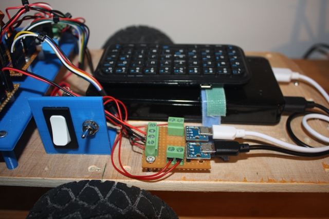
Rodney Robot base. The mini Bluetooth keyboard is stowed when not in use by using a Velcro pad. The keyboard saves having to connect a full size USB keyboard to the Raspberry Pi during testing.

The rear platform holds the Arduino Nano, the Thunderborg and a connection board.

The back of the display showing the Raspberry Pi, camera and Vero board with the audio amplifier. This board is also used as a junction for the I2C connections from the Pi to the Thunderborg.

Now as you can probably tell, Rodney is very much a prototype and as such, there are already plans to change some of the design in the future. The plastic pipe used for the head is too flexible, in the future this may be replaced with a wooden dowel or part of a broom handle. The robot base is rectangular as it was designed for four wheels, now that the robot only has two wheels, the base could be changed for a round design with the wheels protruding through the bottom base. I would like to replace the ten AA batteries and the USB power pack with one battery which is rechargeable in situ, thus allowing the robot to return to a docking station when the battery requires recharging. But as I say that's for the future, before then we need to make the robot fully autonomous.
Points of Interest
In this part, we have now completed Design Goal 3, locomotion controlled by a remote keyboard and/or joystick. I have also produced a circuit diagram and build of material for the current construction.
The next stage will be to add a laser range finder to Rodney to complete design goal 4 and we will also add the IMU to improve the odometry.

History
- 2019/02/05: Initial release
- 2019/03/21: Changed the thunderborg node to publish raw odometry data and add the robot_localization package which will be used to fuse the raw odom data with IMU data
- 2019/04/07:
Added functionality to restore defaults in reconfiguration
PID parameters now not only set from reconfiguration but also from config file
Parameters now use private names
Base height removed as the child frame is the base_footprint not the base_link
Added covariance figures for the odom message
Was incorrectly calculating y velocity. Should only use x velocity and velocity around z