Introduction
In Orbital Mechanics Part 1, I described the basics of orbital mechanics with a program that uses OpenGL to render the 3D graphics. In this Part 2, I have written a similar program using WPF (Windows Presentation Foundation) for the 3D graphics. The user interface is a little different, and I have also added another orbital parameter, the Argument or Periapsis, the orientation of the ellipse in the orbital plane measured from the ascending node to the periapsis, the closest point the satellite comes to the planet.
Using the Code
Download and extract the project, and open OrbitMechWPF.sln with Visual Studio. It consists of a single project. Before running the program, you will first need to set the location of the texture files on your machine in app.config, for example:
<setting name="TextureFileLocation" serializeAs="String">
	<value>C:\MyProjects\OrbitMechWPF\Textures\</value>
</setting>
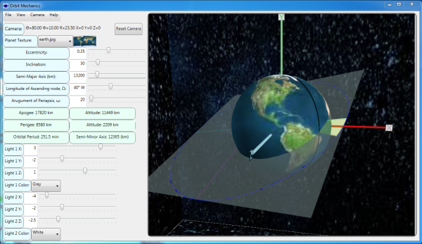
After modifying and saving app.config, build the solution using "Build->Rebuild Solution" from the Visual Studio Main Menu. Use Ctrl-F5 to Start without Debugging and display a WPF Form as shown in the image above.
Orbital Parameters
Using the slider controls in the top left-hand side of the form, the five Orbital Parameters you can modify with this program are:
- Eccentricity - the eccentricity of the orbit's ellipse
- Inclination - the vertical tilt of the ellipse with respect to the orbital plane measured at the ascending node (where the orbit passes upward through the orbital plane)
- Semi-major Axis - the semi-major axis of the orbit's ellipse
- Longitude of the Ascending Node (Omega, Ω) - horizontally orients the ascending node of the ellipse
- Argument or Periapsis - defines the orientation of the ellipse in the orbital plane, as an angle measured from the ascending node to the periapsis
As you change the Orbital Parameters, the corresponding computed orbital values - apogee, perigee, orbital period, and semi-minor axis - are displayed in labels below the sliders.
The Orbital Parameters can be set in any order. Let's start by setting the eccentricity to 0.35 and the semi-major axis to 13200 km by using "File->Open" to open the settings file, SampleOrbitMechWPFSettingsFile.txt (Settings files are discussed below). Next, set the inclination to 30° using the slider or by typing the value into the text box. The orbital plane will be tilted 30° as shown in the image below.

Next, set the Argument of Periapsis to 20° using the slider or by typing the value into the text box. The yellow area shows the orbit's ellipse rotated by 20° as shown in the image below (the actual color is configurable via the ArgumentOfPeriapsisColorFront setting as described below). Note how the longitude line representing Omega is at 0° and intersects the X axis.
Finally, set the Longitude of the Ascending Node (Omega, Ω) to 40° West Longitude using the slider (the text box for Omega is read-only). Note the line of longitude is shown at 40° West Longitude, approximately the longitude of Petrolina, Brazil. West Longitude means Omega has a value of negative 40; positive values of Omega are East Longitude. The orbit should now look like the image below (note that we have rotated our camera theta and zoomed in a little).
The five Orbital Parameters are encapsulated in the OrbitalParameters class, along with the computed orbital quantities (like the orbital period), and the semi-major and semi-minor axes of the ellipse in WPF coordinates, SemiMajorAxisScaled and SemiMinorAxisScaled.
public class OrbitalParameters
{
public float Inclination { get; set; }
public float SemiMajorAxis { get; set; }
public double Eccentricity { get; set; }
public float Omega { get; set; }
public float ArgumentOfPeriapsis { get; set; }
public float SemiMinorAxis { get; set; }
public double Perigee { get; set; }
public double Apogee { get; set; }
public double Period { get; set; }
public float MaxAltitude { get; set; }
public float MinAltitude { get; set; }
public float AxisScaleFactor { get; set; }
public float SemiMajorAxisScaled { get; set; }
public float SemiMinorAxisScaled { get; set; }
public double Focus { get; set; }
public double PlanetRadiusKM { get; set; }
public double Mu { get; set; }
}
Menu Bar
The menu bar has four items: File, View, Camera, and Help.
File
Under "File", there are four options:
- "Open...": allows you to open a previously saved settings file
- "Save As...": allows you to save your settings to a text file
- "Reset": sets the Orbital Parameters and colors to the settings in
Properties.Settings.Default - "Exit": Exits the program
View
As with Part 1, using "View" on the menu bar, you can toggle the drawing of the axes, planet, and orbital plane. With this version, you can also toggle the drawing of the background, ellipse, longitude of the ascending node, and the "flashlights". The background is a box with textures applied, and the flashlights show the directional lights. The code for both the background and flashlights is taken from my Clipping Plane in WPF 3D project.
Camera
Using "Camera" on the menu bar, you can:
- Open the Camera Settings Dialog to set the camera's position (tilt (Φ), rotation (ϴ), and zoom distance).
- Move the camera to point along the positive or negative X, Y or Z axes.
As with Part 1 and as an alternative to using the Camera Settings Dialog, the camera can be moved by using the left, right, up, down, plus and minus keys:
- Up/Down Arrow: tilt camera by phi (Φ) degrees
- Right/Left Arrow: rotate camera by theta (ϴ) degrees
- Plus/Minus: zoom camera In/Out by R units
With this Part 2, you can also pan the camera:
- Ctrl Left-Arrow: pan camera along -X axis
- Ctrl Right-Arrow: pan camera along +X axis
- Shift Up-Arrow: pan camera along +Y axis
- Shift Down-Arrow: pan camera along -Y axis
- Shift Left-Arrow: pan camera along -Z axis
- Shift Right-Arrow: pan camera along +Z axis
The six Camera settings are displayed in the upper left side of the form. The calculation of phi, theta and R is contained in the Camera class which uses the Media3D PerspectiveCamera class. You can reset the camera to the default settings by using "Reset Camera" button, or "Reset Camera" from the menu bar.
Help
"Help" on the menu bar displays a message describing the keystrokes to orient the camera and display the models.
3D Graphics and WPF
Like OpenGL, models in WPF are built as a set of triangles. The triangles are added to a Media3D.MeshGeometry3D object, and the mesh in turn is used to create a Media3D.GeometryModel3D object, a type of Media3D object. The orbital plane created by the DrawOrbitalPlane() method, for example, is a rectangle that is comprised of two right triangles. The rectangle is an instance of the Rectangle3D class which is simply an array of the rectangle's 4 vertices where each vertex is a Point3D:
public class Rectangle3D
{
	public Point3D[] Points;
	public Rectangle3D(Point3D point1, Point3D point2, Point3D point3, Point3D point4)
	{
		Points = new Point3D[] { point1, point2, point3, point4 };
	}
}
The first step is to create the Rectangle3D that encloses the ellipse (note that we are drawing it in the XZ plane, hence the Y coordinate is zero):
Rectangle3D rectOrbitalPlane = new Rectangle3D(
	new Point3D(+orbitalParameters.SemiMajorAxisScaled, +0.0,
                -orbitalParameters.SemiMinorAxisScaled),
	new Point3D(-orbitalParameters.SemiMajorAxisScaled, +0.0,
                -orbitalParameters.SemiMinorAxisScaled),
	new Point3D(+orbitalParameters.SemiMajorAxisScaled, +0.0,
                +orbitalParameters.SemiMinorAxisScaled),
	new Point3D(-orbitalParameters.SemiMajorAxisScaled, +0.0,
                +orbitalParameters.SemiMinorAxisScaled));
The next step is to add the triangles to the mesh. A crucial issue in 3D graphics is to get the winding of the triangle's vertices correct (counter-clockwise, or "right-hand rule" for WPF). Since the orbital plane has a front and back color, it is easy to see how what happens when the winding is the opposite of what is intended. To see this in action, temporarily change the line in OrbitalPlane.cs that adds the second triangle from this:
meshPlane.AddTriangle(rectOrbitalPlane.Points[3],
                      rectOrbitalPlane.Points[2], rectOrbitalPlane.Points[1]);
to this (that is, swap the last two points):
meshPlane.AddTriangle(rectOrbitalPlane.Points[3],
                      rectOrbitalPlane.Points[1], rectOrbitalPlane.Points[2]);
and rebuild and re-run the solution. You will observe that the second triangle has the back color in front, and vice-versa. Remember to change the AddTriangle callback to the correct orientation and rebuild the solution! (Thanks to Rod Stephens for the AddTriangle() method.)
The next step is to create a GeometryModel3D object using the mesh we just added the triangles to. We will use the constructor that takes a material - in this case, a solid color - to make the model visible.
Color frontColor = Properties.Settings.Default.OrbitPlaneColorFront;
Brush orbitalPlaneBrushFront = new SolidColorBrush(frontColor);
DiffuseMaterial orbitalPlaneMaterialFront = new DiffuseMaterial(orbitalPlaneBrushFront);
GeometryModel3D modelOrbitalPlane = new GeometryModel3D(meshPlane, orbitalPlaneMaterialFront);
The GeometryModel3D thus created is returned by the DrawOrbitalPlane() method.
The Model class contains the Media3D.Model3D models that are displayed by the program:
public static class Model
{
	public static Model3D directionalLightModel1 { get; set; }
	public static Model3D directionalLightModel2 { get; set; }
	public static Model3D[] axesModels { get; set; }
	public static Model3D[] backgroundModels { get; set; }
	public static Model3D[] ellipseModels { get; set; }
	public static Model3D[] lightModels1 { get; set; }
	public static Model3D[] lightModels2 { get; set; }
	public static Model3D orbitalPlaneModel { get; set; }
	public static Model3D planetModel { get; set; }
	public static GeometryModel3D longitude { get; set; }
}
The models are created in the InitScene() method. (There is a similar method to create the models from a saved settings file, InitScene(String settings)). For example to create the orbital plane model, the aforementioned DrawOrbitalPlane() method is called:
Model.orbitalPlaneModel = OrbitalPlane.DrawOrbitalPlane(orbitalParameters);
The Media3D.Model3DGroup object is a group of 3-D models treated as though they were a single model. In the DrawScene() method, Model3DGroup modelGroup is initialized by removing all the models: modelGroup.Children.Clear(). Then, depending on what models are on, they are added to the modelGroup's Model3DCollection. For example, if the orbital plane is on, it is added to the collection like this:
if (orbitalPlaneOn)
{
    modelGroup.Children.Add(Model.orbitalPlaneModel);
}
A similar but more complex model is the planet (the more massive body in the 2-body problem). Like the orbital plane just described, it is made of triangles, a mesh of those triangles, and a material. Combining the mesh (and the many triangles it contains) and material with a texture, the DrawPlanet() method
returns a GeometryModel3D object that is added to the modelGroup's Model3DCollection if the planet is on:
Model.planetModel = Planet.DrawPlanet(planetRadiusGLUnits, textureFileDir, textureFile, 180.0);
...
if (planetOn)
{
    modelGroup.Children.Add(Model.planetModel);
}
The planet's texture can be set by using the Planet Texture Combo Box in the top left of the form to select a texture. The same planet textures used in Part 1 are in the Textures\Planets directory. (Thanks to Rod Stephens for the code to draw a texture on a sphere, MakeSphere(). I modified it by adding an additional parameter, double axisRotationDeg. By setting it to 180°, the XYZ axes are aligned with zero degrees longitude, ninety degrees longitude, and the North Pole, respectively. The X axis is the reference direction from which Omega is measured. I also added a DrawLongitude() method to draw a longitude line representing Omega.)
Note that unlike OpenGL, WPF does not have a 3D line drawing primitive. Therefore, to draw the ellipse, the semi-major and semi-minor axes, and the longitude line representing Omega, I used long, thin triangles. You can set the thickness of the lines using the LineThickness setting described below.
3D Transformations
In my Clipping Plane Part 3 project, I described the 3D transformation matrix and how to rotate a model about an axis. In this project, I have encapsulated the rotation transforms in a static method called Transform(OrbitalParameters orbitalParameters) in Utility.cs. For example, here is a snippet from that method to rotate the orbital plane by the orbital inclination:
RotateTransform3D xRotateTransform3D = new RotateTransform3D();
AxisAngleRotation3D xAxisAngleRotation3d = new AxisAngleRotation3D();
xAxisAngleRotation3d.Axis = new Vector3D(1.0, 0.0, 0.0);
xAxisAngleRotation3d.Angle = orbitalParameters.Inclination;
xRotateTransform3D.Rotation = xAxisAngleRotation3d;
Transform3DGroup orbitTransformGroup = new Transform3DGroup();
orbitTransformGroup.Children.Add(xRotateTransform3D);
return orbitTransformGroup;
The transforms for Omega and the Argument of Periapsis are similar. Prior to the rotations, there is a translation such that the focus of the ellipse is at the origin (where the planet and XYZ axes are centered):
TranslateTransform3D xTranslateTransform3D = new TranslateTransform3D();
xTranslateTransform3D.OffsetX = -orbitalParameters.Focus;
Configuration File
There are several settings in app.config you can set to customize OrbitMechWPF. As mentioned previously, before running the program, you must first set the location of the Texture files on your machine, for example:
<setting name="TextureFileLocation" serializeAs="String">
	<value>C:\MyProjects\OrbitMechWPF\Textures\</value>
</setting>
The settings fall into the following categories:
- View Settings
- Camera Settings
- Orbital Parameters
- Colors and Textures
Configuration File - View Settings
<setting name="AxesOn" serializeAs="String">
	<value>True</value>
</setting>
<setting name="BackgroundOn" serializeAs="String">
	<value>True</value>
</setting>
<setting name="EllipseOn" serializeAs="String">
	<value>True</value>
</setting>
<setting name="FlashlightsVisible" serializeAs="String">
	<value>False</value>
</setting>
<setting name="OrbitalPlaneOn" serializeAs="String">
	<value>True</value>
</setting>
<setting name="PlanetOn" serializeAs="String">
	<value>True</value>
</setting>
<setting name="LongitudeOn" serializeAs="String">
	<value>True</value>
</setting>
Configuration File - Camera
The camera parameters can be set as shown below:
<setting name="CameraTheta" serializeAs="String">
	<value>70</value>
</setting>
<setting name="CameraPhi" serializeAs="String">
	<value>10</value>
</setting>
<setting name="CameraR" serializeAs="String">
	<value>27</value>
</setting>
Configuration File - Orbital Parameters
The Orbital Parameters can be set as shown below (you might want to refer to Orbital Mechanics Part 1 if any of these are not familiar to you):
<setting name="Eccentricity" serializeAs="String">
	<value>0.35</value>
</setting>
<setting name="Inclination" serializeAs="String">
	<value>30</value>
</setting>
<setting name="Omega" serializeAs="String">
	<value>-80</value>
</setting>
<setting name="ArgumentOfPeriapsis" serializeAs="String">
	<value>20</value>
</setting>
<setting name="SemiMajorAxis" serializeAs="String">
	<value>13200</value>
</setting>
<setting name="MaxAltitude" serializeAs="String">
	<value>297</value>
</setting>
<setting name="MinAltitude" serializeAs="String">
	<value>111</value>
</setting>
<setting name="PlanetRadiusKM" serializeAs="String">
	<value>6371.1</value>
</setting>
<setting name="Mu" serializeAs="String">
	<value>398600.8</value>
</setting>
Configuration File - Colors, Textures, LineThickness
The colors, textures, and line thickness can be set as shown below:
<setting name="TextureFileLocation" serializeAs="String">
	<value>C:\MtProjects\OrbitMechWPF\Textures\</value>
</setting>
<setting name="PlanetTexture" serializeAs="String">
	<value>earth.jpg</value>
</setting>
<setting name="OrbitPlaneColorFront" serializeAs="String">
	<value>#04787878</value>
</setting>
<setting name="OrbitPlaneColorBack" serializeAs="String">
	<value>#44FF0000</value>
</setting>
<setting name="BackgroundColor" serializeAs="String">
	<value>#FF808080</value>
</setting>
<setting name="EllipseColorBack" serializeAs="String">
	<value>#BB00EEEE</value>
</setting>
<setting name="EllipseColorFront" serializeAs="String">
	<value>#FF0000FF</value>
</setting>
<setting name="LineThickness" serializeAs="String">
	<value>0.05</value>
</setting>
<setting name="LongitudeColor" serializeAs="String">
	<value>#FF000000</value>
</setting>
<setting name="ArgumentOfPeriapsisColorFront" serializeAs="String">
	<value>#55F5FF44</value>
</setting>
<setting name="ArgumentOfPeriapsisColorBack" serializeAs="String">
	<value>#55FFC61C</value>
</setting>
Settings File
You can save your:
- Current view (Axes On/Off, Background On/Off, Ellipse On/Off, Flashlights Visible/Invisible, Longitude On/Off, Orbital Plane On/Off, and Planet On/Off)
- Orbital Parameters (Eccentricity, Inclination, Semi-major Axis, Omega, and Argument or Periapsis)
- Camera settings (CameraTheta, CameraPhi and CameraR)
- The name of the texture file selected for the planet
- The flashlight locations and colors
in a text file by using "File->Save As..." from the menu bar. The file contains a comma-separated list of values preceded by an Md5 hash. When you start OrbitMechWPF at a later time, you can restore your settings from that file by using "File->Open..." and specifying the name of the text file.
History


 General
  News
News  Suggestion
  Question
  Bug
Bug  Answer
  Joke
Joke  Rant
Rant  Admin
Admin