Introduction
This project is about building an Internet of Things (IoT), “connected” device pretty much from scratch. What I’ve built is essentially a custom-designed SigFox enabled Arduino (based on a low-power version of the Arduino ProMini). I’ll take you through from concept through “bread-boarding”, Arduino programming, Fritzing diagrams, VeroBoard, PCB Design, PCB Printing, Soldering and Surface Mount considerations all the way through to a finished product. All software and hardware I’ve built is open source and I’ve included links to the GitHub source files.
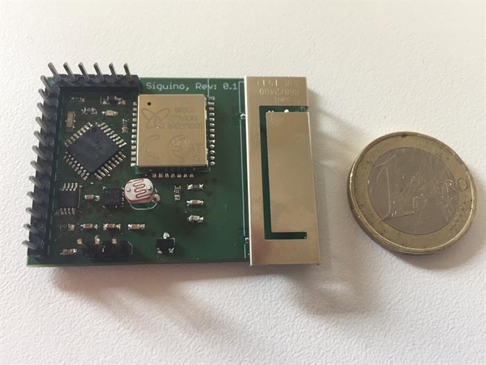
The final custom PCB prototype:
Background
This project arose mainly from a desire to work with, and learn more about, low level hardware and IoT devices in general. I had been working exclusively with software development over many years, and more recently mainly in management roles, so when the opportunity arose to do something new, I wanted to experiment outside my comfort zone (I had not had any direct hardware experience since I completed my college degree, many years ago!). With IoT becoming more and more ubiquitous, and frankly more and more interesting, over the last number of years, it felt like a really good time to start building something in this area. The rollout of the SigFox network in Ireland, where I’m based, seemed to make some form of SigFox enabled sensor device an obvious choice, but the more I looked into this, the more apparent it became that there wasn’t a “ready-to-go” development device for me to start working with. And so, the concept of the SigFox based Arduino (or “Siguino”) arose.
1. Breadboarding
As all good maker projects start, I started with Breadboarding out a conceptual circuit. This involves working out functions you want your device to have and from that, what components you are going to use. So for me, I wanted my device to:
-
Be Arduino based & low power (so I based it on a Pro Mini)
-
Have the ability to send messages over the SigFox network: for this, you need a SigFox chip, of which there are many options. I chose the SFMR10 from Wisol for two reasons:
-
It is a send-only chip rather than a transceiver and I had no plans for two way communications
-
There was a DevKit available for it (very useful for breadboarding and prototyping, and this DevKit from Yadom works very well)
-
Have four basic sensors:
-
Temperature (initially, I used a DS18B20 but this doesn't work well at voltages below 3v so I swtiched to a AT30TS750A)
-
Light Level (a standard photocell)
-
Magnetic detection “Hall effect” for door open/close: AH9246-W-7
-
Movement detection: I experimented with trip switches, mercury switches, etc. but given I was primarily thinking of a board for makers, ultimately an accelerometer was a better choice as it opens up the native possibilities of the board. I went with an LIS3DH. Note: The breakout board for this component from AdaFruit is *not* low power, though the raw chip itself is. Details of the issue are here.
The end result was a rather messy (but functional!) set of components:

However, I recommend spending a little extra time putting together a neater version when you have everything working using special breadboard "Jumper" wires (see below):
2. Arduino Code
Next is writing the basic code to get your breadboarded device to do what you want it to do. Some of this is very standard and included in many of the existing example code for each component, for example, getting the temperature from a DS18B20, covered well here, looks like this:
#include <DallasTemperature.h>
#include <OneWire.h>
#define ONE_WIRE_BUS 2
OneWire oneWire(ONE_WIRE_BUS);
DallasTemperature temp_sensor(&oneWire);
void setup(){
Serial.begin(9600);
temp_sensor.begin();
Serial.println("DS18B20 Temperature Test\n\n");
delay(300);
}
void loop(){
Serial.print("Requesting temperatures...");
temp_sensor.requestTemperatures();
Serial.print("Temperature is: ");
float temp_reading = temp_sensor.getTempCByIndex(0);
Serial.println(temp_reading);
delay(1000);
}
For low power usage of an Arduino pro mini, there are a number of options in terms of 3rd party libraries. I chose the open source low power library by RocketScream available on GitHub here. There is a good article on using this library here and here, and the sample usage for this project would be:
#include "LowPower.h"
void setup()
{
}
void loop()
{
LowPower.powerDown(SLEEP_8S, ADC_OFF, BOD_OFF);
}
SigFox Messages
The Wisol chip I chose for this project can be communicated with using standard AT commands (basic examples are included with the product datasheet). For this project, I needed only two functions:
Send Message
I wrote a wrapper for the low level AT commands, allowing easier command sending such as to test the device and sending messages:
String send_at_command(String command, int wait_time){
altSerial.println(command);
delay(wait_time);
return recv_from_sigfox();
}
void test_sigfox_chip(){
Serial.println("Sigfox Comms Test\n\n");
altSerial.begin(9600);
delay(300);
Serial.println("Check awake with AT Command...");
chip_response = send_at_command("AT", 50);
Serial.println("Got response from sigfox module: " + chip_response);
Serial.println("Sending comms test...");
chip_response = send_at_command("AT", 50);
Serial.println("Comms test response from sigfox module: " + chip_response);
chip_response = send_at_command("AT$I=10", 50);
Serial.println("Dev ID response from sigfox module: " + chip_response);
chip_response = send_at_command("AT$I=11", 50);
Serial.println("PAC Code response from sigfox module: " + chip_response);
}
chip_response = send_at_command("AT$SF=" + hex_bits, 10000);
Serial.println("Reponse from sigfox module: " + chip_response);
Enter Low Power (Sleep) Mode
For this, I opted for the basic sleep mode, though this chip also supports a “deep sleep” option. It just didn’t seem worth it to move from ~1.5uA to <1uA as a 1.5uA quiescent current drain was more than acceptable for our purposes. The sleep / wake cycle code looks like this:
void set_sigfox_sleep(bool go_sleep){
String chip_response;
if (go_sleep){
chip_response = send_at_command("AT$P=1", 100);
Serial.println("Set sleep response: " + chip_response);
}else{
altSerial.end();
pinMode(TX_PIN, OUTPUT);
digitalWrite(TX_PIN, LOW);
delay(100);
altSerial.begin(9600);
}
}
Bit Packing
One thing that would be of particular use for SigFox message sending is bit packing, since SigFox messages are a maximum of 12 bytes, you really need to be squashing as much data as possible into the message. For example, assume the “temperature” returned by the temperature sensor is going to be a float between -40 and +80 degrees Celsius, such as 22.46 or -4.67 or something. A float in C++ uses 4 bytes of memory, but you don’t want to use up 4 bytes of your 12 byte message sending a number like this if it is not necessary. For most purposes, you only need to know a temperature value to a half degree of accuracy, so if your range of possible temperatures is from -40 to +80 for example, and you only need accuracy to a half degree then you only have 240 possible values you might need to send, so you’ve squashed them all into 8 bits (1 byte), essentially:
0b00000000 [0] = -40
0b00000001 [1] = -39.5
0b00000010 [2] = -39
…
0b11101111 [239] = 79.5
0b11110000 [240] = 80
In fact, I chose only 7 bits for temperature (-10 to +50 in half degree accuracy), 5 bits for light level (from 0 to 1000 essentially) and a single bit for open/close or device move, and 4 bits for a message sequence number so I can spot any missed messages. So for my basic sensors, I only needed to use 18 bits of my 12 bytes of available message space, packed like this:
I adapted a set of bit packing functions (original code here) that would take all the sensor data as well as the number of bits I wanted to use for each and pack them into a single 12 byte value:
#ifndef BITPACKER_H_INCLUDED
#define BITPACKER_H_INCLUDED
#include <stdint.h>
#define BIT(n) ( 1UL<<(n) ) //UL = unsigned long,
#define BIT_SET(y, mask) ( y |= (mask) )
#define BIT_CLEAR(y, mask) ( y &= ~(mask) )
#define BIT_FLIP(y, mask) ( y ^= (mask) )
#define BIT_MASK(len) ( BIT(len)-1 )
#define BF_MASK(start, len) ( BIT_MASK(len)<<(start) )
#define BF_PREP(x, start, len) ( ((x)&BIT_MASK(len)) << (start) )
#define BF_GET(y, start, len) ( ((y)>>(start)) & BIT_MASK(len) )
#define BF_SET(y, x, start, len) \
( y= ((y) &~ BF_MASK(start, len)) | BF_PREP(x, start, len) )
namespace BitPacker {
static uint32_t get_packed_message_32
(unsigned int values[], unsigned int bits_used[], int num_vals){
uint32_t retval = 0x0;
int j = 0;
for (int i=0;i<num_vals;i++){
BF_SET(retval, values[i], j, j + bits_used[i]);
j += bits_used[i];
}
return retval;
}
static uint64_t get_packed_message_64
(unsigned int values[], unsigned int bits_used[], int num_vals){
uint64_t retval = 0x0;
int j = 0;
for (int i=0;i<num_vals;i++){
BF_SET(retval, values[i], j, j + bits_used[i]);
j += bits_used[i];
}
return retval;
}
}
#endif // BITPACKER_H_INCLUDED
3. Fritzing & Veroboarding
Prior to getting stuck into custom designing a PCB circuit for your device, it is very worthwhile trying to nail down a smaller, neater prototype circuit. I opted for a Stripboard version of this circuit, though Veroboard is just as usable. The end result should be a much neater and tighter version of the circuit, which is very useful in helping trim down the final PCB design (remember as a rule of thumb, the larger the PCB, the higher the cost). It also gives you a good idea about what sort of housing may be required for your product.
Fritzing is a great piece of software for laying out Stripboard or Veroboard circuits, allowing you to completely produce a virtual circuit, which you can then simply copy on your stripboard. There are good tutorials on Fritzing, for example, see here. My prototype circuit looked like this in Fritzing:
Which led to this actual (working) circuit:
4. PCB Design and Printing
Now you get onto the PCB design. I used Autodesk Eagle, which is an excellent piece of software and free to use for small boards (<80cm). There are lots of component libraries, including good 3rd party libraries (e.g., all of the SparkFun and AdaFruit components).
A tutorial on how to use this product would be its own CodeProject article, but in fact, there are some fantastic resources already available on this front. I really recommend the SparkFun tutorials, I learnt everything I needed to from these three tutorials:
- Install and Setup
- Creating Schematics
- Board Layout and Routing
It takes some time to complete all three, but they are well worth it. Some tips I would suggest from my own experience:
-
Save often!
-
Always recheck DRC rules after every change, no matter how small. Recheck after ground pour, even if the change *should* not have affected the ground pour.
-
When routing with very small components (e.g., FPGA surface mount components), try not to have any holes underneath the component. Whilst this is allowable and should work fine, it becomes an issue when you are hand soldering / surface mounting components for prototype testing in the absence of professional tooling (e.g., solder reflow ovens, pick & place machinery, etc.). It’s very hard to be sure when hand applying solder / solder paste that it does not sit under the component and flow into a routing hole underneath (where you cannot see), and it's easy to forgot when routing just how small some of these components are.
So don't do this:
Instead, do this:
- As above, but with larger components, try not to have routing holes too near the component legs / pads for the same reason.
The final fully routed board layout looked like this:
5. Soldering and Surface Mounted Components (SMC)
This was a big unknown for me at the start of this project: how to build prototypes that included surface mounted components? It’s much easier to use plated through hole (PTH) components for prototyping (e.g., breadboarding) but you wouldn’t choose PTH components for a final product as SMC are smaller and neater, so what happens when you design your PCB layout with your ideal SMC components and you get it printed and you want to put it all together and test it, but you don’t have any Surface Mount machinery like a pick and place machine or a solder reflow oven? There are tutorials and Youtube videos about building your own reflow oven [e.g., here] from various toaster or toaster microwaves, but really if you’re building your own circuit, that kind of departure from the focus is a bit time-consuming I think. And it turns out it is mostly unnecessary as you can hand-solder almost all surface mount components anyway with the right practice. Also, you can use relatively inexpensive solder air gun to make the job easier.
I used the excellent YouTube channel EEVBlog to teach myself the basics of how to do SMC soldering, and in the end, I was hand soldering everything down to 0402 components (so small you will lose them if you breathe too heavily on them!). See component size comparison chart:
I wouldn’t recommend using 0402 components in your circuit (I had no choice in mine as they were used as part of an RF net under the antenna and larger components could have affected the antenna performance). In fact, 0602 components are also very small and tricky enough to solder, but with a bit of practice, it’s all very doable. I would recommend when ordering your PCBs to order and extra couple of boards in the first batch purely for soldering practice as you will very likely make a mess of your first attempt!
Finally, in terms of tools needed:
-
Soldering Iron: I really recommend getting a good soldering iron. It is definitely worth paying a bit more for a quality iron as the cheaper ones just aren’t good enough (in my experience - I bought a cheap one on Amazon and a couple of weeks later, I ditched it and bought a much better one and everything was much easier). I went for this one from circuit specialists and it works a charm.
-
Hot air soldering gun: I also bought a hot air gun and while this has proved trickier to use than I’d hoped (getting the air pressure right so you don’t blow small components off the board is an art form!), it has made soldering some of the smaller VFLGA package ICs like the LIS3DH much easier (I’m not even sure how I would have done this with a soldering iron alone, though I have read that it is possible). It also makes removing components very easy when you mess something up.
-
Tweezers: A good quality, very fine tip set of tweezers is essential (I went for a set of them, something like this). You will be picking up some very small components, so these are essential kit.
-
Eye Loupe / magnifying glass: You will need to be zooming in on your soldering to check for bad solder, solder bridges, blobs, missed pins, etc. I found a jewellers loupe, preferably with a light in-built very useful.
6. Power Consumption Measurement
This was a surprisingly difficult but very important part of the process to complete. I wanted this device to be ultra low power so that it could work from a small battery (a 900mAh CR2 battery was chosen in the end) for as close to 1 year as possible. This meant making sure that the quiescent current (the constant current draw) was as small as possible, down into the low uA range, while accounting for the occasional higher current draw during message sending. Whilst there are a number of circuits and methods of assessing the current requirements of a circuit, most do not have good resolution for the very low end and manual mechanisms such as an ammeters connected across the power supply lines was cumbersome to use and also only gave snapshots of the current usage at a given time (and in some cases did not react fast enough for any reliable measurement).
Of the various options I tried to solve this problem, the only one that worked in the end was the Power Profiling Kit from Nordic Semiconductor. It wasn’t too expensive (at around $100 or so for both the PPK and the base board) and it worked really well (though my one gripe is that it was Windows Only - I tried to get it to work on linux as it is a python program but sadly I could only make it work reliably on Windows. That’s not such a big issue in general, it’s just that all my other software I run on Linux so it required a reboot into Windows to run this software… I didn’t try to run it on Wine).
It produces both a constant view of the power consumption down to a very low resolution (<1uA) and also a running average for a time window (which is exactly what we needed for our battery life calculations):
7. Atmega Bootloader Programming
Once you receive your raw Atmega chips (i.e., not those already on an Arduino, just the chip itself), it will not have any bootloader programmed, so you won't be able to communicate with it and load programs via the Arduino IDE until you bootload it. This is best done using a separate Arduino Uno (other boards are possible, but these instructions assume a standard Uno):
- Bootloader: Use Atmega chip programmer by Nick Gammon
- Found here: https://github.com/nickgammon/arduino_sketches
- Download ZIP file
- Extract Atmega_Board_Programmer folder (e.g. to Arduino IDE Libraries dir)
- Open
Atmeaga_Board_Programmer sketch - Connect standard Arduino Uno to PC
- Set board to "Arduino/Genuino Uno" and set correct port.
- Upload sketch
- Disconnect Uno and connect target chip as follows:
- Uno Target
- D10 -> Reset
- D11 -> MOSI
- D12 -> MISO
- D13 -> SCK
- Gnd -> Gnd
- +5V -> Vcc
- Power up Uno / Set port / Run Serial Monitor 115200 Baud.
- Bootloader should run immediately and show results in serial monitor window. Follow instructions in Serial Window (e.g. "
L" for Load Bootloader) - NOTE: Bootloader will set chip to use internal 8MHz clock (this can be modified if you have an external crystal, see notes in sketch)
8. PCB Printing, Purchasing Components, Manufacturing and Assembly
At various stages, from breadboarding to bulk manufacturing, you will need to make use of a number of resources:
Hardware Components
In order to breadboard your circuit, you will need components such as the various resistors, capacitors, sensors, integrated circuits, etc. You can find some of these mainstream sites like Amazon, but I would recommend some of the hardware specific sites as a better option. I used DigiKey mainly and found them very good, but Mouser and Farnell are also good.
PCB Printing
Once you have designed your PCB and created the Gerber files, you will need someone to print this for you. I used Multi-CB and found them very good and very timely as well as very competitively priced. The only downside is that there is no online payment processing option as they only deal with businesses so a bank transfer is required. Having said that, the service is good and the boards produced are good quality and there’s plenty of options also. Depending on where you're based, there may be other PCB manufacturers available to you, there's a section on this page under "Picking a PCB Manufacturer" that might be worth a look.
PCB Manufacturing
Ok, so you’ve got your PCB fully designed, you’ve bought all your components and hand-soldered and tested your last prototype, now you want to get it manufactured in bulk, what to do? I found PCB Cart and got a very reasonable quote for this, which included assembly and the programming of the Atmega chip with my default program, but at this point in time, I have not yet had the boards manufactured so I can't comment beyond the quote stage as to their quality / delivery.
9. Backend Development
So you’ve built your device, and it sends messages on the SigFox network (essentially to the SigFox servers)... now what!? How are you going to process those messages and what are you going to do with them?
SigFox Callback
The first thing to do is to have the SigFox server forward on any messages received by your device to some web server / web services that you control. There are many options with the SigFox system on how to do this, but I think the easiest is to build your own RESTful web services (see next section) and have the SigFox servers make a HTTP(S) request to your new services with the message data. This can be done within the SigFox backend by using a Callback Mechanism for your device, where you can specify the posted variables or URL parameters as needed from a list of available variables, including the raw message data:
RESTFUL Web Services
RESTful web services are the modern API and ubiquitous on the web and there are many ways to create them. I decided to build mine using the newer language Go mainly as it was a language I wanted to learn more about, and because it’s an easy to deploy via Docker. The basic structure of a web service (saving to a MongoDB database) in Go looks like this:
func NewSensorData(w http.ResponseWriter, r *http.Request) {
var dataResource SensorDataResource
err := json.NewDecoder(r.Body).Decode(&dataResource)
if err != nil {
common.DisplayAppError(
w,
err,
"Invalid Sensor Data format",
500,
)
return
}
sensorData := &dataResource.Data
context := NewContext()
defer context.Close()
c := context.DbCollection("SensorData")
repo := &db.SensorDataRepository{c}
repo.Create(sensorData)
if j, err := json.Marshal(SensorDataResource{Data: *sensorData}); err != nil {
common.DisplayAppError(
w,
err,
"An unexpected error has occurred",
500,
)
return
} else {
w.Header().Set("Content-Type", "application/json")
w.WriteHeader(http.StatusCreated)
w.Write(j)
}
}
And most of the simple web services you might build for basic data processing of raw data from the SigFox servers would be of a similar structure.
One thing that would be of particular use for SigFox message parsing would be the bit unpacking (since SigFox messages are a maximum of 12 bytes, you really need to be squashing as much data as possible into the message, and as such you will probably be bit packing data as I did here for this project). The corresponding Go code for unpacking the data that was bit packed with the earlier Arduino code, looks like this:
func bit(n uint64) uint64 {
    return 1<<n
}

func bit_set(y uint64, mask uint64) uint64 {
    return y | mask
}

func bit_clear(y uint64, mask uint64) uint64 {
    return y & ^mask
}

func bit_flip(y uint64, mask uint64) uint64 {
    return y ^ mask
}

func bit_mask(len uint64) uint64 {
    return bit(len) - 1
}

func Bf_mask(start uint64, len uint64) uint64 {
    return bit_mask(len) << start
}

func Bf_prep(x uint64, start uint64, len uint64) uint64 {
    return (x & bit_mask(len)) << start
}

func Bf_get(y uint64, start uint64, len uint64) uint64 {
    return (y>>start) & bit_mask(len)
}

func Bf_set(y uint64, x uint64, start uint64, len uint64) uint64 {
    return (y & ^Bf_mask(start, len)) | Bf_prep(x, start, len)
}
IFTTT Integration
Finally, in terms of making your device accomplish something beyond data logging, probably the easiest way to integrate it with other devices or ecosystems is to make use of the existing infrastructure for integration and use If This Then That (IFTTT) which is an amalgamation of many different APIs and systems. Once you connect your device to this system, all the existing follow on actions become available. For example, “If [your device sends x] then [send email to y] or [make Alexa say Y] or [Turn on Philips lights in y room]” or any myriad of other options. There are good articles on how best to connect into the IFTTT system here.
Next Steps & Moving Forward
At the moment for me, I am investigating getting a 3D housing for this device created as well as going through the SigFox device certification program, tweaking the antenna to get the most out of it and trying to get the first production run of my device organised (all via Kickstarter if anyone is interested in the device itself rather than the process of building it). But the main purpose of my embarking on this project was always learning about hardware and IoT technology and so all of the Arduino code and hardware is open source and on Github, and I hope detailing the process I went through here will be of use to others interested in getting into this space. Thanks for reading!
History
- 14th September, 2017: Initial version created


 General
  News
News  Suggestion
  Question
  Bug
Bug  Answer
  Joke
Joke  Praise
  Rant
Rant  Admin
Admin 


